


2-4
Alignment and Adjustment
Samsung Electronics
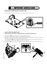
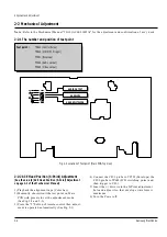
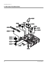
2-2 Mechanical Adjustment
Note : Refer to the Mechanical Manual “TS-10 (AC68-01405A)” for the adjustment and confirmation of ass’y deck.
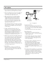
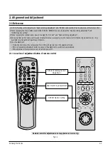
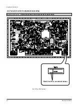
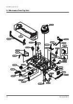
2-2-1 The number and position of test point
Test point :
TP601 (Control Pulse)
TP602 (H’D S/W -Trigger)
TP301 (Envelope)
TP302 (Audio output)
TP303 (Video output)
Fig. 2-4 Location of Test point (Main PCB-Top View)
AUDIO OUTPUT
HEAD SWITCHING
ENVELOPE
2-2-2 ACE Head Position (X-Point) Adjustment
(See the 2-2-1(d) ACE Head Position (X-Point) Adjustment
on page 2-2 of the Mechanical Manual)
1) Playback the alignment tape (Color bar).
2) Momently short-circuit the test point on Main
PCB with pincers to set the adjustment mode.
(See Fig. 2-2 and 2-3)
3) Press the “5” button of remote control then adjust-
ment is operated automatically. (See Fig. 2-1)
4) Connect the CH-1 probe to TP301 (Envelope) the
CH-2 probe to TP602 (H’D switching pulse) and
then trigger to CH-1.
5) Insert the (-) driver into the X-Point adjustment
hole and adjust it so that envelope waveform is
maximum.
6) Turn the Power off.
Содержание VR5140C
Страница 10: ...2 6 Alignment and Adjustment Samsung Electronics MEMO ...
Страница 18: ...Exploded View and Parts List 3 8 Samsung Electronics MEMO ...
Страница 28: ...4 10 Samsung Electronics Electrical Parts List MEMO ...
Страница 32: ...Schematic Diagrams 5 4 Samsung Electronics 5 2 Logic Ø ˆ Œ ˇ ...
Страница 34: ...Schematic Diagrams 5 6 Samsung Electronics 5 3 Audio Video ˇ ˆ Ø Œ ...
Страница 36: ...Schematic Diagrams 5 8 Samsung Electronics 5 4 Hi Fi Option Œ ˇ ...
Страница 40: ...Schematic Diagrams 5 12 Samsung Electronics 5 7 Display LED Lamp VR8140C 5140C ...
Страница 59: ...1 18 Samsung Electronics Disassembly and Reassembly MEMO ...


