background image

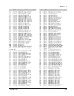
R329

2007-000671

R-CHIP;2KOHM,5%,1/10W,DA,TP,2012

R330

2001-000221

R-CARBON;1.2KOHM,5%,1/8W,AA,TP,1.8X3.2M

R331

2001-000878

R-CARBON;6.2KOHM,5%,1/8W,AA,TP,1.8X3.2M

R332

2007-001224

R-CHIP;9.1KOHM,5%,1/10W,DA,TP,2012

R334

2007-000586

R-CHIP;22KOHM,5%,1/10W,DA,TP,2012

R335

2007-000931

R-CHIP;470OHM,5%,1/10W,DA,TP,2012

R336

2007-000267

R-CHIP;1.8KOHM,5%,1/10W,DA,TP,2012

R337

2007-000502

R-CHIP;2.2OHM,5%,1/10W,DA,TP,2012

R338

2007-000449

R-CHIP;180OHM,5%,1/10W,DA,TP,2012

R339

2007-000468

R-CHIP;1KOHM,5%,1/10W,DA,TP,2012

R340

2007-000468

R-CHIP;1KOHM,5%,1/10W,DA,TP,2012

R341

2007-000586

R-CHIP;22KOHM,5%,1/10W,DA,TP,2012

R342

2007-000300

R-CHIP;10KOHM,5%,1/10W,DA,TP,2012

R344

2001-000331

R-CARBON;12KOHM,5%,1/8W,AA,TP,1.8X3.2MM

R345

2007-000572

R-CHIP;220OHM,5%,1/10W,DA,TP,2012

R346

2007-000774

R-CHIP;33KOHM,5%,1/10W,DA,TP,2012

R347

2007-000468

R-CHIP;1KOHM,5%,1/10W,DA,TP,2012

R348

2007-000872

R-CHIP;4.7KOHM,5%,1/10W,DA,TP,2012

R349

2007-001001

R-CHIP;510OHM,5%,1/10W,DA,TP,2012

R350

2007-001001

R-CHIP;510OHM,5%,1/10W,DA,TP,2012

R352

2007-000981

R-CHIP;5.6KOHM,5%,1/10W,DA,TP,2012

R353

2007-000300

R-CHIP;10KOHM,5%,1/10W,DA,TP,2012

R354

2007-000757

R-CHIP;330KOHM,5%,1/10W,DA,TP,2012

R356

2007-000565

R-CHIP;220KOHM,5%,1/10W,DA,TP,2012

R357

2007-000565

R-CHIP;220KOHM,5%,1/10W,DA,TP,2012

R358

2001-000008

R-CARBON;15KOHM,5%,1/8W,AA,TP,1.8X3.2MM

R359

2007-000738

R-CHIP;30KOHM,5%,1/10W,DA,TP,2012

R360

2001-000977

R-CARBON;8.2KOHM,5%,1/8W,AA,TP,1.8X3.2M

R361

2007-000964

R-CHIP;5.1KOHM,5%,1/10W,DA,TP,2012

R362

2001-000786

R-CARBON;47KOHM,5%,1/8W,AA,TP,1.8X3.2MM

R363

2001-000258

R-CARBON;1.8KOHM,5%,1/8W,AA,TP,1.8X3.2M

R364

2007-000941

R-CHIP;47KOHM,5%,1/10W,DA,TP,2012

R367

2007-000689

R-CHIP;3.3MOHM,5%,1/10W,DA,TP,2012

R399

2001-000786

R-CARBON;47KOHM,5%,1/8W,AA,TP,1.8X3.2MM

R401

2001-000780

R-CARBON;470OHM,5%,1/8W,AA,TP,1.8X3.2MM

R402

2001-000780

R-CARBON;470OHM,5%,1/8W,AA,TP,1.8X3.2MM

XT301

2801-003610

CRYSTAL-UNIT;3.579545MHz,8ppm,28-AAA,S,1

TM-BLOCK

C401

2203-000260

C-CERAMIC,CHIP;10nF,10%,50V,X7R,TP,2012

C402

2401-000414

C-AL;10uF,20%,16V,GP,TP,4x7,5

C403

2202-000797

C-CERAMIC,MLC-AXIAL;10NF,30%,16V,Y5S,TP,

C405

2401-001545

C-AL;47uF,20%,25V,GP,TP,6.3x7mm,2.5

C406

2202-000797

C-CERAMIC,MLC-AXIAL;10NF,30%,16V,Y5S,TP,

C407

2202-000807

C-CERAMIC,MLC-AXIAL;22nF,+80-20%,25V,Y5V

C409

2202-002037

C-CERAMIC,MLC-AXIAL;100nF,80-20%,50V,Y5V

C410

2203-000609

C-CERAMIC,CHIP;22nF,10%,50V,X7R,TP,2012

SW401

3408-001042

SWITCH-SLIDE;DC 12V,100mA,-,OFF-ON,-

TM401

AC40-00007A

TM-BLOCK;115VD025AP,NTSC-M,115VD025AP,Y

INPUT-OUTPUT PARTS

C801

2401-002144

C-AL;47uF,20%,16V,GP,TP,5x11,5

C802

2401-001479

C-AL;470uF,20%,10V,GP,TP,-,-

C803

2401-002042

C-AL;220uF,20%,10V,GP,TP,6.3x11,5

C804

2203-000274

C-CERAMIC,CHIP;0.01nF,0.25pF,50V,NP0,TP,

C805

2401-001730

C-AL;10uF,20%,50V,GP,TP,5x11,2.5

C8M2

2203-000802

C-CERAMIC,CHIP;33nF,10%,50V,X7R,TP,2012

JK801

AC37-20001H

JACK-RCA;DPAM-,4P,MONO,PI3.3

L801

2701-000168

INDUCTOR-AXIAL;3.3uH,5%,2.5x3.4mm

L802

3301-000297

CORE-FERRITE BEAD;AA,3.6x1.2x5.7mm,1400,

Q801

0501-000303

TR-SMALL SIGNAL;KSA733,PNP,250mW,TO-92,T

R801

2001-000969

R-CARBON;75OHM,5%,1/8W,AA,TP,1.8X3.2MM

R802

2001-000025

R-CARBON;75OHM,5%,1/4W,AA,TP,2.4X6.4MM

R803

2007-001239

R-CHIP;910OHM,5%,1/10W,DA,TP,2012

R804

2007-001166

R-CHIP;75OHM,5%,1/10W,DA,TP,2012

R8M1

2001-000786

R-CARBON;47KOHM,5%,1/8W,AA,TP,1.8X3.2MM

R8M2

2001-000878

R-CARBON;6.2KOHM,5%,1/8W,AA,TP,1.8X3.2M

R8M3

2001-000766

R-CARBON;43KOHM,5%,1/8W,AA,TP,1.8X3.2MM

R8M6

2007-000029

R-CHIP;0OHM,5%,1/10W,DA,TP,2012

FUNCTION KEY MATRIX PARTS

C7L01

2401-002165

C-AL;100uF,20%,16V,GP,TP,6.3x7,5

D701

0401-000101

DIODE-SWITCHING;1N4148,100V,200mA,DO-35,

D702

0401-000101

DIODE-SWITCHING;1N4148,100V,200mA,DO-35,

D703

0401-000101

DIODE-SWITCHING;1N4148,100V,200mA,DO-35,

D704

0401-000101

DIODE-SWITCHING;1N4148,100V,200mA,DO-35,

D705

0401-000101

DIODE-SWITCHING;1N4148,100V,200mA,DO-35,

D706

0401-000101

DIODE-SWITCHING;1N4148,100V,200mA,DO-35,

D740

0401-000101

DIODE-SWITCHING;1N4148,100V,200mA,DO-35,

R742

2001-000734

R-CARBON;4.7KOHM,5%,1/8W,AA,TP,1.8X3.2M

R743

2001-000734

R-CARBON;4.7KOHM,5%,1/8W,AA,TP,1.8X3.2M

R744

2001-000734

R-CARBON;4.7KOHM,5%,1/8W,AA,TP,1.8X3.2M

SW701

3404-000165

SWITCH-TACT;12V,50mA,160gf,6x6mm,SPST

SW702

3404-000165

SWITCH-TACT;12V,50mA,160gf,6x6mm,SPST

SW703

3404-000165

SWITCH-TACT;12V,50mA,160gf,6x6mm,SPST

SW704

3404-000165

SWITCH-TACT;12V,50mA,160gf,6x6mm,SPST

SW705

3404-000165

SWITCH-TACT;12V,50mA,160gf,6x6mm,SPST

SW706

3404-000165

SWITCH-TACT;12V,50mA,160gf,6x6mm,SPST

DISPLAY PCB

C701

2202-000173

C-CERAMIC,MLC-AXIAL;1nF,10%,50V,Y5P,TP,1

C702

2202-000797

C-CERAMIC,MLC-AXIAL;10NF,30%,16V,Y5S,TP,

C703

2401-002165

C-AL;100uF,20%,16V,GP,TP,6.3x7,5

D707

0402-000127

DIODE-RECTIFIER;1N4002,100V,1A,DO-41,TP

D708

0401-000101

DIODE-SWITCHING;1N4148,100V,200mA,DO-35,

DT701

0703-001090

LED DISPLAY;GRN/RED,5,8,50x18.5mm

Q701

0501-000398

TR-SMALL SIGNAL;KSC945,NPN,250mW,TO-92,T

Q702

0501-000398

TR-SMALL SIGNAL;KSC945,NPN,250mW,TO-92,T

Q703

0501-000398

TR-SMALL SIGNAL;KSC945,NPN,250mW,TO-92,T

Q704

0501-000398

TR-SMALL SIGNAL;KSC945,NPN,250mW,TO-92,T

Q705

0501-000398

TR-SMALL SIGNAL;KSC945,NPN,250mW,TO-92,T

Q706

0501-000398

TR-SMALL SIGNAL;KSC945,NPN,250mW,TO-92,T

Q707

0501-000398

TR-SMALL SIGNAL;KSC945,NPN,250mW,TO-92,T

Q708

0501-000398

TR-SMALL SIGNAL;KSC945,NPN,250mW,TO-92,T

Q709

0501-000290

TR-SMALL SIGNAL;KSA643-Y,PNP,500mW,TO-92

Q710

0501-000290

TR-SMALL SIGNAL;KSA643-Y,PNP,500mW,TO-92

Q711

0501-000290

TR-SMALL SIGNAL;KSA643-Y,PNP,500mW,TO-92

Q712

0501-000290

TR-SMALL SIGNAL;KSA643-Y,PNP,500mW,TO-92

Q713

0501-000290

TR-SMALL SIGNAL;KSA643-Y,PNP,500mW,TO-92

R701

2001-000290

R-CARBON;10KOHM,5%,1/8W,AA,TP,1.8X3.2MM

R703

2001-000290

R-CARBON;10KOHM,5%,1/8W,AA,TP,1.8X3.2MM

R704

2001-000969

R-CARBON;75OHM,5%,1/8W,AA,TP,1.8X3.2MM

R705

2001-000290

R-CARBON;10KOHM,5%,1/8W,AA,TP,1.8X3.2MM

R706

2001-000969

R-CARBON;75OHM,5%,1/8W,AA,TP,1.8X3.2MM

R707

2001-000290

R-CARBON;10KOHM,5%,1/8W,AA,TP,1.8X3.2MM

R708

2001-000969

R-CARBON;75OHM,5%,1/8W,AA,TP,1.8X3.2MM

R709

2001-000290

R-CARBON;10KOHM,5%,1/8W,AA,TP,1.8X3.2MM

R710

2001-000969

R-CARBON;75OHM,5%,1/8W,AA,TP,1.8X3.2MM

R711

2001-000290

R-CARBON;10KOHM,5%,1/8W,AA,TP,1.8X3.2MM

R712

2001-000969

R-CARBON;75OHM,5%,1/8W,AA,TP,1.8X3.2MM

R713

2001-000290

R-CARBON;10KOHM,5%,1/8W,AA,TP,1.8X3.2MM

R714

2001-000969

R-CARBON;75OHM,5%,1/8W,AA,TP,1.8X3.2MM

R715

2001-000290

R-CARBON;10KOHM,5%,1/8W,AA,TP,1.8X3.2MM

R716

2001-000969

R-CARBON;75OHM,5%,1/8W,AA,TP,1.8X3.2MM

R717

2007-000493

R-CHIP;2.2KOHM,5%,1/10W,DA,TP,2012

R719

2007-000493

R-CHIP;2.2KOHM,5%,1/10W,DA,TP,2012

R721

2001-000449

R-CARBON;2.2KOHM,5%,1/8W,AA,TP,1.8X3.2M

R723

2001-000449

R-CARBON;2.2KOHM,5%,1/8W,AA,TP,1.8X3.2M

R725

2001-000449

R-CARBON;2.2KOHM,5%,1/8W,AA,TP,1.8X3.2M

R727

2001-000290

R-CARBON;10KOHM,5%,1/8W,AA,TP,1.8X3.2MM

R752

2001-000969

R-CARBON;75OHM,5%,1/8W,AA,TP,1.8X3.2MM

RM701

AC32-00002A

MODULE-REMOCON;-,GP1U291Q,38KHZ,-,7.3X13

Loc.No

Part No 

Description ; Specification 

Remark

4-4

Samsung Electronics

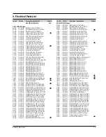
Electrical Parts List

Loc.No

Part No 

Description ; Specification 

Remark

Содержание VR400PVR400PC

Страница 1: ...t 3 Exploded View and Parts List 4 Electrical Parts List 5 Schematic Diagrams Manual VIDEO CASSETTE RECORDER CONTENTS For mechanical disassembly and adjustment refer to the Mechanical Manual DX 9R AC68 00001A EJECT STOP REW F F POWER PLAY SERVICE MANUAL VR400G VR400PC SV 400GP 400GUP 400GUM ELECTRONICS Samsung Electronics Co Ltd NOV 2000 Printed in Korea AC68 01289A ...

Страница 2: ...ee Fig 2 3 When Slider S T are approached in the position of unloading rotate holder Clutch counterclockwise after inserting screw driver in the hole of frame s bottom in order to wind the unwounded tape Refer to Fig 3 If you rotate Gear Worm Wheel continuously when tape is in state of unwinding you may cause a tape contamination by grease and tape damage Be sure to wind the unwounded tape in the ...

Страница 3: ...ot exceed 0 5 milliamp Reverse the power plug prongs in the AC outlet and repeat the test 6 X ray Limits The picture tube is designed to prohibit X ray emissions To ensure continued X ray protection replace the picture tube only with one that is the same type as the original Fig 1 1 AC Leakage Test 7 Antenna Cold Check With the unit s AC plug disconnected from the AC source connect an electrical j...

Страница 4: ... instrument s ground lead to the instrument chassis ground before connecting the positive lead always remove the instrument s ground lead last 17 Observe the original lead dress especially near the following areas Antenna wiring sharp edges and especially the AC and high voltage power supplies Always inspect for pinched out of place or frayed wiring Do not change the spacing between components and...

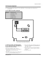
Страница 5: ...es buttons 0 9 is available for all adjustment regardless of chassis 5 How to adjustment Intermittently short circuit the test point on Main PCB with pincets to set the adjustment mode If the corresponding adjustment button is pressed the adjustment is performed automatically If the adjustment is completed be sure to turn the power off 2 1 1 Location of adjustment button of remote control Fig 2 1 ...

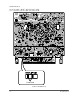
Страница 6: ...2 2 Samsung Electronics Alignment and Adjustment 2 1 2 Test point location for adjustment mode setting Fig 2 2 Main PCB Bottom View Short Circuit ...

Страница 7: ...E 2 2 2 ACE Head Position X Point Adjustment See the 2 2 1 d ACE Head Position X Point Adjustment on page 2 2 of the Mechanical Manual 1 Playback the alignment tape Color bar 2 Intermittently short circuit the two test points on Main PCB to set the adjustment mode See Fig 2 2 3 Press the 5 button of remote control then adjust ment is operated automatically See Fig 2 1 4 Connect the CH 1 probe to T...

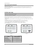
Страница 8: ...TOP button is pressed the selected number is changes reversed color See Fig 2 4 5 Press the MENU button of remote control again to store the option number save is displayed for a second as shown Fig 2 5 and this setting is completed 6 Turn the Power off 1 NVRAM Option is adjusted at production line basically 2 In case Micom IC601 and NVRAM IC603 EEPROM is replaced be sure to set the corresponding ...

Страница 9: ...Samsung Electronics 3 1 3 Exploded View and Parts List Page 3 1 Cabinet Assembly 3 2 3 2 Mechanical Parts Top Side 3 4 3 3 Mechanical Parts Bottom Side 3 6 ...

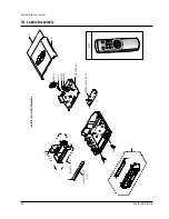
Страница 10: ...List 3 2 Samsung Electronics 3 1 Cabinet Assembly 157 153 FULL DECK S N A BRACKET FRAME S N A 1 22 21 MAIN PCB S N A BOTTOM COVER S N A TM401B 200 CN303B CN605B 55 56 101 155 S601A LD601A S602A UT01 S N A Service Not Available ...

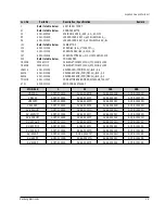
Страница 11: ...SENSOR POM M90 44 BLK X 9 S602A AC61 21008A HOLDER SENSOR POM M90 44 BLK X 9 TM401B AC61 11054A CONNECTOR BOARD MONO HIPS94 HB T2 0 100 UT01 AC59 00013U REMOCON ASSY 14KEY MODELS 1 21 101 200 VR400G AC97 01091A AC64 00407B AC64 00404B AC39 10200N VR400P AC97 01092A AC64 00407C AC64 00404C AC39 10200N VR400PC AC97 01093A AC64 00407D AC64 00404C AC39 10200N VR400RC AC97 01094A AC64 00407E AC64 00404...

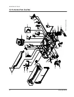
Страница 12: ...chanical Parts Top Side G001 K250 K248 K110 K502 K350 K330 K182 K140 K490 K530 K240 G532 G420 G450 K546 G510 B410 B440 B444 B446 B448 B452 G527 G520 G480 G680 OPTIONAL S N A S N A S N A S N A S N A G530 K340 B473 K188 G555 G546 S N A Service Not Available S N A ...

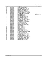
Страница 13: ...M2 6 L5 0 ZPC G520 AC66 30539A LEVER 9 GUIDE ASSY X 9 TS X 9 G527 AC61 60553A SPRING 9 GUIDE ES SUS304 WPB OD3 1 0 G530 AC33 00002A HEAD FE HVFHP0038A X 9 G532 AC60 10519A SCREW TAP TITE PH M2 6 L8 ZPC G546 AC66 30535A LEVER FL DOOR POM M90 44 BLK X 9 G555 AC59 90403A UNIT PINCH ASSY X 9 K110 AC66 10267A REEL DISK S X 9 POM K140 AC66 10268A REEL DISK T X 9 POM K182 AC66 30524A LEVER IDLER POM K188...

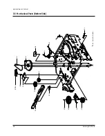
Страница 14: ...d View and Parts List 3 6 Samsung Electronics 3 3 Mechanical Parts Bottom Side G542 B560 B484 B458 B500 B488 B462 OPTIONAL S N A S N A S N A S N A B456 K222 K200 K225 K221 B570 B238 S N A Service Not Available ...

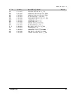
Страница 15: ...AP TITE PH M2 6 L5 ZPC YE B484 AC66 20580A GEAR LOADING DRIVE POM SW 01 M1 0 Z32 B488 AC66 30543A LEVER S LOAD ASSY X 9 B500 AC66 30542A LEVER T LOAD ASSY X 9 B560 AC31 00006A MOTOR CAPSTAN DMVCMC07JR B570 AC60 10514A SCREW CAPSTAN PH M2 6 L6 G542 AC66 60051A BELT PULLEY 5CM 70 2 2 71 3 X 9 K200 AC61 21012A HOLDER CLUTCH ASSY X 9 K221 AC66 20581A GEAR CENTER ASSY POM M O 5 HIGHT T K222 AC60 30306A...

Страница 16: ...Exploded View and Parts List 3 8 Samsung Electronics MEMO ...

Страница 17: ...METAL 2 2Kohm 1 1 8W AA TP 1 8x3 2m VA1SS1 1405 001026 VARISTOR 470V 600A 9x7mm TP ZD1SR1 0403 000571 DIODE ZENER UZP43B 43V 40 46V 1W DO 41 T S M P S PARTS FREE Voltage BD1SS1 AC27 92001M INDUCTOR 70UH M RT BFS3565R2F BD1SS2 3301 000297 CORE FERRITE BEAD AA 3 6x1 2x5 7mm 1400 BD1SS4 AC27 92001M INDUCTOR 70UH M RT BFS3565R2F C1SD01 2201 000795 C CERAMIC DISC 10nF 10 400V Y5P TP 15x1 C1SD05 2201 00...

Страница 18: ...27 2203 001245 C CERAMIC CHIP 0 082nF 5 50V NP0 TP 201 C628 2401 002068 C AL 33uF 20 16V GP TP 5x11 5 C629 2203 001579 C CERAMIC CHIP 15nF 10 50V NP0 TP 2012 C630 2401 002144 C AL 47uF 20 16V GP TP 5x11 5 C631 2203 000192 C CERAMIC CHIP 100nF 80 20 50V Y5V TP C632 2203 001077 C CERAMIC CHIP 0 056nF 5 50V NP0 TP 201 C633 2203 000716 C CERAMIC CHIP 3 3nF 10 50V X7R TP 2012 C634 2203 001077 C CERAMIC...

Страница 19: ...92 C CERAMIC CHIP 100nF 80 20 50V Y5V TP C334 2203 000989 C CERAMIC CHIP 47nF 10 50V X7R TP 2012 C335 2203 000989 C CERAMIC CHIP 47nF 10 50V X7R TP 2012 C336 2203 000192 C CERAMIC CHIP 100nF 80 20 50V Y5V TP C337 2401 002144 C AL 47uF 20 16V GP TP 5x11 5 C338 2401 000913 C AL 22uF 20 16V GP TP 5x11 5 C339 2401 002144 C AL 47uF 20 16V GP TP 5x11 5 C340 2202 002037 C CERAMIC MLC AXIAL 100nF 80 20 50...

Страница 20: ...OHM 5 1 8W AA TP 1 8X3 2MM R8M6 2007 000029 R CHIP 0OHM 5 1 10W DA TP 2012 FUNCTION KEY MATRIX PARTS C7L01 2401 002165 C AL 100uF 20 16V GP TP 6 3x7 5 D701 0401 000101 DIODE SWITCHING 1N4148 100V 200mA DO 35 D702 0401 000101 DIODE SWITCHING 1N4148 100V 200mA DO 35 D703 0401 000101 DIODE SWITCHING 1N4148 100V 200mA DO 35 D704 0401 000101 DIODE SWITCHING 1N4148 100V 200mA DO 35 D705 0401 000101 DIOD...

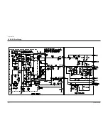
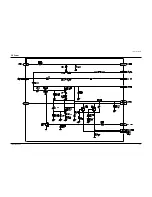
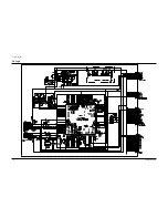
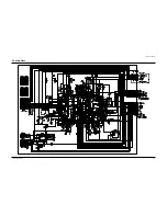
Страница 21: ...nics 5 1 5 Schematic Diagrams Block Identification of Main PCB 5 2 5 1 S M P S 120 Voltage 5 3 5 2 S M P S Free Voltage 5 4 5 3 Power 5 5 5 4 Logic 5 6 5 5 Audio Video 5 7 5 6 TM Block Input Output 5 8 5 7 Display 5 9 ...

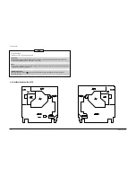
Страница 22: ...r the electrostatically sensitive ES devices section of this service manual Note Do not use the part number shown on this drawing for ordering The correct part number is shown in the parts list may be slightly different or amended since this drawing was prepared Important safety notices Components identified with the mark have the special characteristics for safety When replacing any of these comp...

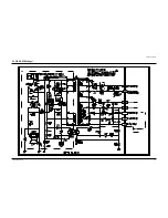
Страница 23: ...Schematic Diagrams Samsung Electronics 5 3 5 1 S M P S 120 Voltage ...

Страница 24: ...Schematic Diagrams 5 4 Samsung Electronics 5 2 S M P S Free Voltage ...

Страница 25: ...Schematic Diagrams Samsung Electronics 5 5 5 3 Power ...

Страница 26: ...Schematic Diagrams 5 6 Samsung Electronics 5 4 Logic ...

Страница 27: ...Schematic Diagrams Samsung Electronics 5 7 5 5 Audio Video ...

Страница 28: ...Schematic Diagrams 5 8 Samsung Electronics 5 6 TM Block Input Ouput ...

Страница 29: ...Schematic Diagrams Samsung Electronics 5 9 5 7 Display ...

Страница 30: ...Schematic Diagrams 5 10 Samsung Electronics MEMO ...

Страница 31: ...sembly and Reassembly 2 Alignment and Adjustment VHS DECK CONTENTS 3 File with the SERVICE MANUAL MECHANICAL MANUAL DX 9R ELECTRONICS Samsung Electronics Co Ltd NOV 1998 Printed in Korea AC68 00001A MECHANICALManual ...

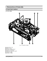
Страница 32: ...ˆ Ø Fig 1 1 Top parts Location 1 Œ BRACKET FL TOP GEAR FL CAM ˇ MOTOR LOADING ASS Y LEVER FL ARM ASS Y ˆ HOLDER FL CASSETTE ASS Y Ø LEVER FL DOOR SLIDER FL DRIVE 1 Disassembly and Reassembly 1 1 Deck Parts Locations 1 1 1 Top View ...

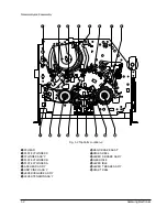
Страница 33: ... Parts Location 2 Œ FE HEAD PLATE CYLINDER C ˇ CYLINDER ASS Y PLATE CYLINDER B ˆ PLATE CYLINDER A Ø ACE HEAD ASS Y UNIT PINCH ASS Y LEVER 9 GUIDE ASS Y LEVER TENSION ASS Y BAND BRAKE ASS Y Ô DISK S REEL LEVER S BRAKE ASS Y Ò GEAR IDLE Ú LEVER IDLE Æ LEVER T BRAKE ASS Y ı DISK T REEL ...

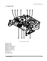
Страница 34: ...s 1 3 1 1 2 Bottom View Œ ˇ ˆ Ø Ô Fig 1 3 Bottom Parts Location Œ GEAR JOINT 1 GEAR JOINT 2 ˇ BRAKET GEAR MOTOR CAPSTAN ASS Y ˆ LEVER T LOAD ASS Y Ø GEAR LOADING DRIVE LEVER S LOAD ASS Y HOLDER CLUTCH ASS Y BELT PULLEY SLIDER CAM Ô SLEEVE TENSION ...

Страница 35: ...e Take care not to change assembly direction Œ 2 SCREWS BRACKET FL TOP 1 2 2 Lever FL Door Removal 1 Rotate the Lever FL Door Œ in the direction of arrow ÒAÓ 2 Release the Hook remove the Lever FL Door Œ in the direction of arrow ÒBÓ HOOK Œ LEVER FL DOOR A B 1 2 Main Deck Fig 1 4 Bracket FL Top Removal Fig 1 5 Lever FL Door Removal ...

Страница 36: ...mpletely Note Be sure to insert Lever FL Cassette R in the direction of ÒAÓ to prevent separation and breakage of the Lever FL Cassette R at disassembling and reassembling Œ HOLDER FL CASSETTE ASS Y LEVER FL CASSETTE R BOSS A BOSS B RAIL C RAIL D A B 1 2 4 Lever FL Arm Ass y Removal 1 Remove the Lever FL Door Refer to Fig 1 5 2 Remove the Holder FL Cassette AssÕy Refer to Fig 1 6 3 Release the Hoo...

Страница 37: ...the direction of arrow Refer to Fig 1 8 Œ SLIDER FL DRIVE 1 2 6 Bracket Gear Gear FL Cam Gear Joint 1 2 Removal 1 Remove screw Œ 2 Lift the Bracket Gear 3 Remove the Gear FL Cam ˇ 4 Lift the Gear Joint 2 Gear Joint 1 ˆ Œ SCREW BRACKET GEAR ˇ GEAR FL CAM ˆ GEAR JOINT 1 GEAR JOINT 2 Fig 1 8 Slider FL Drive Removal Fig 1 9 Bracket Gear Gear FL Cam Gear Joint 1 2 Removal ...

Страница 38: ...ng Point 3 Œ GEAR JOINT 1 GEAR JOINT 2 ˇ SLIDER CAM TIMING POINT 1 GEAR FL CAM GEAR WORM WHEEL POST TIMING POINT 2 TIMING POINT 3 1 2 8 Holder Worm Gear Worm Gear Worm Wheel Removal 1 Release the Hook A in the direction of arrow and remove the Holder Worm Œ 2 Remove the Gear Worm 3 Remove the Gear Worm Wheel ˇ After remov ing the Gear FL Cam as shown Fig 1 9 Note Secure the Hook A after installing...

Страница 39: ...S Load Ass y Removal 1 Remove the Belt Pulley Refer to Fig 1 29 2 Remove the Gear Loading Drive Œ after releasing Hook A in the direction arrow as shown in detail drawing 3 Remove the Slider Cam 4 Remove the Lever T S Load AssÕy ˇ Œ GEAR LOADING DRIVE ˇ LEVER T LOAD ASS Y HOOK A SLIDER CAM LEVER S LOAD ASS Y Fig 1 12 Motor Loading Ass y Removal Fig 1 13 Gear Loading Drive Slider Cam Lever T S Load...

Страница 40: ... 1 TIMING POINT 2 TIMING POINT 3 1 2 12 Lever Tension Ass y Band Brake Ass y Sleeve Tension Removal 1 Remove the Spring Tension Œ 2 In bottom side of Deck remove the Sleeve Tension after rotating it right or left as lifting locking edge of Sleeve Tension 3 Remove the side ÒaÓ of the Band Brake AssÕy in the direction of arrow ÒAÓ from the Lever Tension AssÕy ˇ 4 Remove the side ÒbÓ of the Band Brak...

Страница 41: ...care not to be folded and trans formed spring Brake at removing or reinstalling ˇ SPRING BRAKE LEVER T BRAKE ASS Y Œ LEVER S BRAKE ASS Y HOOK A HOOK C HOOK B 1 2 14 Lever Idle Ass y Removal 1 Push the Lever Idle Œ in the direction of arrow ÒAÓ ÒBÓ 2 Lift the Lever Idle Œ Assembly 1 Apply oil in two Bosses of Lever Idle Œ 2 Assemble the Gear Idle with the Lever Idle Œ Note When replacing the Gear I...

Страница 42: ... S T Reel Removal 1 Lift the Disk S T Reel Œ DISK T REEL Œ DISK S REEL 1 2 16 Holder Clutch Ass y Removal 1 Remove the Washer Slit Œ 2 Lift the Holder Clutch AssÕy HOLDER CLUTCH ASS Y Œ WASHER SLIT Fig 1 18 Disk S T Reel Removal Fig 1 19 Holder Clutch Ass y Removal ...

Страница 43: ... Base 2 Lift the Lever Up Down AssÕy Œ about 35 degree Refer to Fig 1 21 3 Insert Ring of the Gear Center AssÕy in the Guide ˆ of the Lever Up Down AssÕy Œ 4 Insert the Gear Center AssÕy in the post Ø on Main Base 5 Push down the Lever Up Down AssÕy Œ for lock ing of the Hook Note 1 Take care not to separate and loose the Spring Up Down 2 When assembling the Gear Center AssÕy donÕt push down too m...

Страница 44: ... 2 20 Unit Pinch Ass y Plate Joint Spring Pinch Drive Removal 1 Lift the Unit Pinch AssÕy Œ 2 Remove the Plate Joint from Lever Pinch Drive 3 Remove the Spring Pinch Drive ˇ Note 1 Take extreme care not to touch the grease on the Roller Pinch 2 When reinstalling be sure to apply grease on the post pinch roller Œ UNIT PINCH ASS Y PLATE JOINT ˇ SPRING PINCH DRIVE Fig 1 22 Guide Cassette Door Removal...

Страница 45: ...ion of arrow Note 1 Take extreme care not to touch the grease on the tape Guide Post 2 After reinstalling check the bottom side of the Post 9 Guide to stick to the top side of Main Base LEVER 9 GUIDE ASS Y Œ SPRING 9 GUIDE 1 2 22 FE Head Removal 1 Remove the screw Œ 2 Lift the FE Head Œ SCREW FE HEAD Fig 1 24 Lever 9 Guide Ass y Removal Fig 1 25 FE Head Removal ...

Страница 46: ...connector of ACE Head AssÕy 2 Remove the screw Œ 3 Lift the ACE Head AssÕy Œ SCREW ACE HEAD ASS Y 1 2 24 Slider S T Ass y Removal 1 Move the Slider S T AssÕy Œ to slot and then lift it to remove Refer to arrow SLIDER T ASS Y Œ SLIDER S ASS Y Fig 1 26 ACE Head Removal Fig 1 27 Slider S T Ass y Removal ...

Страница 47: ...ylinder C 3 Take care not to touch the Cylinder AssÕy with screw driver at reinstalling the Plate Cylinder C ˆ SCREW CYLINDER ASS Y Œ SCREW PLATE CYLINDER C ˇ SCREW PLATE CYLINDER B Ø PLATE CYLINDER A 1 2 26 Belt Pulley Removal 1 Remove the Belt Pulley Œ Note Take extreme care not to touch the grease on Belt Pulley Œ at assembling or reassembling Œ BELT PULLEY Fig 1 28 Cylinder Ass y Removal Fig 1...

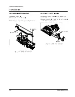
Страница 48: ... 29 How to Eject the Cassette Tape If the unit does not operate on condition that is inserted into housing ass y 1 Remove the Holder worm Œ and the Gear Worm 2 Turn the Gear Worm Wheel ˇ counterclockwise with screw driver Refer to arrow Œ HOLDER WORM GEAR WORM SCREW DRIVER ˇ GEAR WORM WHEEL Fig 1 31 Motor Capstan Ass y Removal Fig 1 32 3 When Slider S T are approached in the position of unloading ...

Страница 49: ...STAN SHAFT 9 GUIDE POST 3 GUIDE POST GUIDE ROLLER S T O O O O O O O CYLINDER ASS Y O O O O O O O O O FE HEAD O O O O O O O ACE HEAD O O O O O O O O O PINCH ROLLER O O O O O O O O O POST REEL S T 3 3 3 3 3 SLEEVE TENSION 3 3 3 3 3 POST CENTER 3 3 3 3 3 LEVER IDLE BOSS 2Point 3 3 3 3 3 CAPSTAN MOTOR PULLEY O O O O O BELT PULLEY O O O O O O O HOLDER CLUTCH ASS Y O O O O O O O O O GEAR CENTER ASS Y O ...

Страница 50: ...LER GUIDE ROLLER S GUIDE ROLLER T 8 GUIDE POST 9 GUIDE POST CAPSTAN SHAFT ACE HEAD 3 GUIDE POST 2 Alignment and Adjustment 2 1 Tape Transport System and Adjustment Locations The tape transport system has been adjusted precisely in the factory Alignment is not necessary except for the following 1 Noise observed on the screen 2 Tape damage 3 Parts replacement in the tape transport system Lower flang...

Страница 51: ...ghtly turn the screw A tilt adjust on the ACE head assÕy 4 Reconfirm the ACE head height Fig 2 5 Tape Guide Check 2 2 1 c AUDIO AZIMUTH ADJUSTMENT 1 Load alignment tape Mono scope and playback the NTSC 7KHz PAL 6KHz signal 2 Connect channel 1 scope probe to audio output test point 3 Adjust screw B to achieve maximum audio level See Fig 2 3 2 2 1 d ACE HEAD POSITION X POINT ADJUSTMENT 1 See page 5 ...

Страница 52: ...he video RF envelope at the exit side 4 If the section A in Fig 2 7 does not meet the speci fication adjust the guide roller S up or down 5 If the section B in Fig 2 7 does not meet the speci fication adjust the guide roller T up or down Fig 2 6 Envelope Waveform Adjustment a a b c d c b d a 63 b c d Fig 2 7 Adjustment Points A B A B H D SWITCHING PULSE ENVELOPE 6 Play back the Mono Scope alignmen...

Страница 53: ...ng with T 120 E 120 The video envelope should meet the specification as shown in Fig 2 10 In SP mode A should equal B If the head gap is wide upper cylinder should be checked A B Fig 2 10 Envelope Output and Output Level 2 2 5 Tape Wrinkle Check 1 Run the T 160 E 180 tape in the playback FPS RPS and Pause modes and observe tape wrinkle at each guide 2 If excessive tape wrinkle is observed perform ...

Страница 54: ...cting it with Back Tension Meter 1 0mm 0 5mm ˇ LEVER TENSION ASS Y Œ DISK S REEL ADJUSTING ADJUSTING SLIT 1 3 Fig 2 13 Tension Pole and Back Tension Adjustment 1 Remove the holder cassette assÕy and then push the lever FL Arm R to the direction of loading 2 Push the lever tension drive Œ in the direction of arrow See Fig 2 11 3 Turn the gear worm wheel clockwise so that ÒTiming PointÓ of the slide...

Страница 55: ...2 6 Samsung Electronics Alignment and Adjustment MEMO ...

Отзывы: