background image

Alignment and Adjustments

5-15

Samsung Electronics

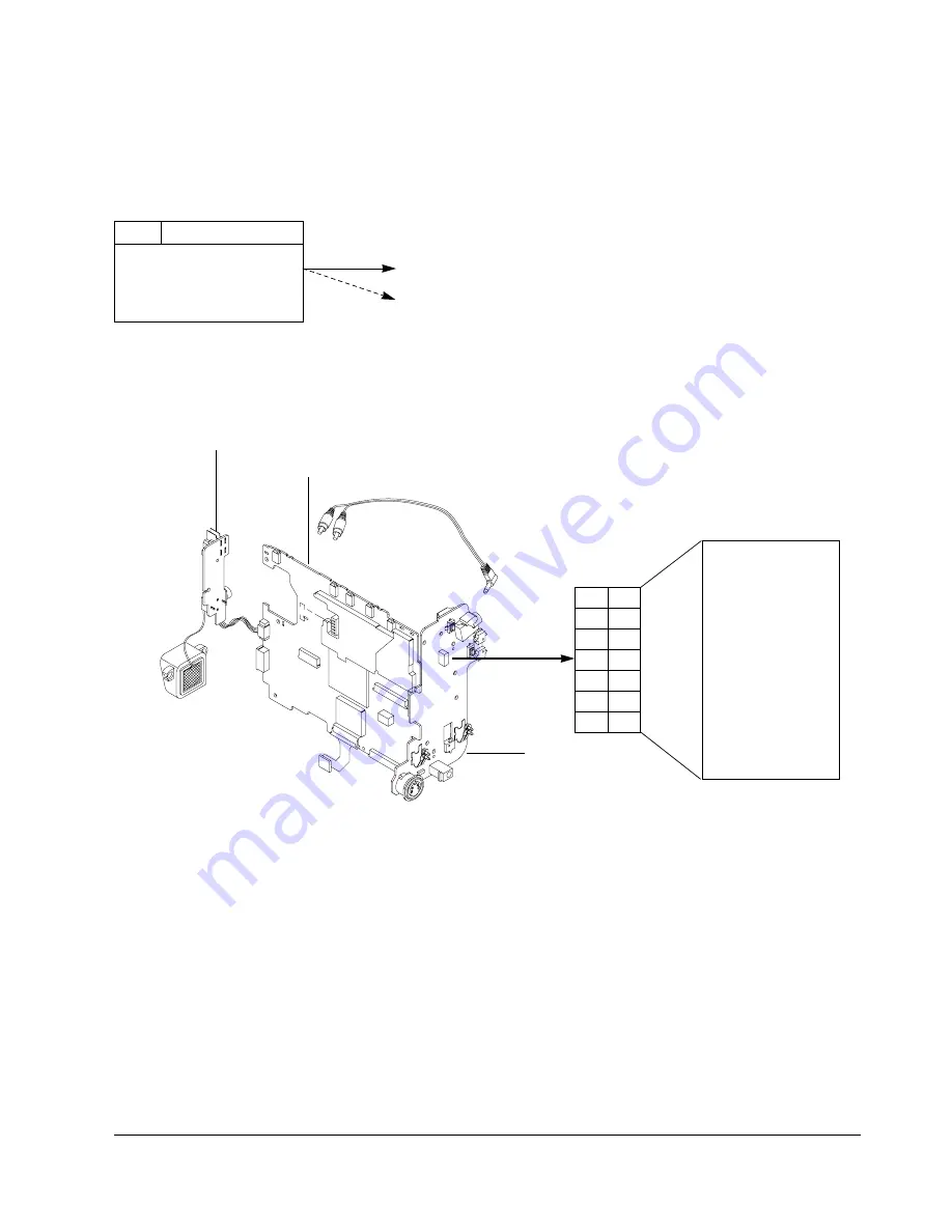
Note 2 : How to connect video out signal.

-Connect the video cable to ass’y A/V Jack. 

5-5-2 VCR Section

Note 1 : From this point forward, the structure of every adjustment is as follows.

Test point

Step      Adjustment Item

1. Mode and input signal/

alignment tape

2. Test point and ADJ. part
3. Result and Remarks

ADJ. point

Fig. 5-21 Video Signal Connection

14

13

VIDEO OUT

12
11
10

9
8
7
6
5
4
3
2
1

NC

PB RF

AUDIO OUT

HD SW

VCR UNREG

JIG CS

VCR UNREG

JIG SCK
SS GND

JIG SO

JIG DETECT

JIG SI

AUDIO GND

14

MAIN PCB

REAR PCB

FRONT PCB

CN452

13

12

11

10

9

8

7

6

5

4

3

2

1

Содержание VP-L900

Страница 1: ...rating Description 8 Troubleshooting 9 Block Diagram 10 Wiring Diagram 11 PCB Diagrams 12 Schematic Diagrams Manual 8mm CAMCORDER CONTENTS TRAINING MANUAL VP L900 VP L906 VP L907 ELECTRONICS Samsung Electronics Co Ltd FEB 2004 Printed in Korea AD82 00037A PAL This Service Manual is a property of Samsung Electronics Co Ltd Any unauthorized use of Manual can be punished under applicable Internationa...

Страница 2: ...ot exceed 0 5 milliamp Reverse the power plug prongs in the AC outlet and repeat the test 6 X ray Limits The picture tube is designed to prohibit X ray emissions To ensure continued X ray protection replace the picture tube only with one that is the same type as the original Fig 1 1 AC Leakage Test 7 Antenna Cold Check With the unit s AC plug disconnected from the AC source connect an electrical j...

Страница 3: ... instrument s ground lead to the instrument chassis ground before connecting the positive lead always remove the instrument s ground lead last 17 Observe the original lead dress especially near the following areas Antenna wiring sharp edges and especially the AC and high voltage power supplies Always inspect for pinched out of place or frayed wiring Do not change the spacing between components and...

Страница 4: ...ight System LCD Screen Connectors General Video 2 rotary heads Helical scanning FM Audio FM monaural system PAL color CCIR standard Hi8 or 8mm SP 20 051 mm sec Record SP only Playback SP only P6 120 120 min P6 120 approx 8 min CCD Charge Coupled Device 22x 3 6 79 2 mm 1 6 37 mm Inner Auto wide macro 0 3 lux visible 2 5 inch 123k TFT Mini jack 1 Vp p 75 ohms Unbalanced Mini jack 7 7 dBs imp less th...

Страница 5: ...Product Specification 2 2 MEMO ...

Страница 6: ...AMERA mode 12 EASY EASY works in CAMERA mode 13 VIDEO LIGHT VP L906 L907 only 3 LIGHT PLAY STILL 4 REC SEARCH FF 5 DATE TIME STOP 7 EVF 10 LCD 11 CUSTOM 12 EASY 2 REC SEARCH REW 6 TAPE EJECT 13 VIDEO LIGHT 1 LENS 9 Remote Sensor 8 MIC ENGLISH Getting to Know Your Camcorder 10 14 MENU ON OFF see page 26 MENU ON OFF works in CAMERA and PLAYER mode 15 ENTER MF see page 26 ENTER works in MENU mode MF ...

Страница 7: ...907 only 33 External MIC VP L906 L907 only MIC 37 SNAP SHOT D ZOOM Getting to Know Your Camcorder OSD On Screen Display ENGLISH 12 You can turn the OSD on off by setting the Display menu on off The TITLE DATE TIME EASY and CUSTOM functions can be operated even after the OSD is turned off The OSD is displayed in the viewfinder and the LCD monitor a Zoom position see page 30 Indicates zoom position ...

Страница 8: ...rn is acivated v PB DSE see page 57 Shows that the PB DSE mode is active w VOLUME see page 56 x EASY CUSTOM Shows when the easy or custom mode is active y LIGHT VP L906 L907 only Shows when the Light is switched on z Remocon OFF VP L906 L907 only Indicates the remocon off mode is activated Getting to Know Your Camcorder Accessories Supplied with Camcorder ENGLISH 14 Make sure that the following ba...

Страница 9: ...the power switch to CAMERA mode 2 Press the Self Timer button on the remote until the appropriate setting is displayed on the LCD WAIT 10S SELF 30S WAIT 10S SELF END 3 To start the delayed recording press the START STOP button After waiting for 10 seconds recording starts If you have selected SELF 30S recording stops automatically after 30 seconds If you have selected SELF END press START STOP aga...

Страница 10: ...f the reach of the children Should the battery be swallowed consult a doctor immediately 2 1 3 4 Preparing Connecting the Power Source ENGLISH 18 There are two ways to connect to a power source Using the AC Power Adapter used for indoor recording Using the Battery Pack used for mobile outdoor recording To use the AC Power Adapter 1 Connect the AC Power Adapter to the AC power cord 2 Connect the AC...

Страница 11: ...n if the power is turned off battery will be discharged Note The battery pack may be slightly charged at the time of purchase Preparing To use the Battery Pack ENGLISH 19 1 4 2 3 OFF ENGLISH Preparing 20 Using the Battery Pack The continuous recording times given in the table are approximate Actual recording time may differ depending on usage Notes The battery pack should be recharged in a room te...

Страница 12: ...s Tips for Battery Identification A charge mark is provided on the battery pack to help you remember whether it has been charged or not Two colours are provided red and black you may choose which one indicates charged and which indicates discharged 1 2 3 4 5 6 Preparing Inserting and Ejecting a Cassette ENGLISH 22 There are several cassette types depending on Colour system used Recording playback ...

Страница 13: ...TART STOP button Shooting starts and REC should be displayed on the LCD REC X XX XX CAMERA BATTERY ENGLISH Basic Shooting 24 b To stop shooting press the red START STOP button again When recording stops STBY will be displayed on the LCD When a cassette is loaded and the camcorder is left in STANDBY mode for over 5 minutes without being used it will turn off automatically To use it again push the r...

Страница 14: ... or on a table for greater stability Do not forget to breathe gently 5 Put your eye firmly against the viewfinder 6 Use the viewfinder frame as a guide to determine the horizontal plane 7 Whenever possible use a tripod Basic Shooting Adjusting the LCD ENGLISH 26 You can view the image you are recording or watch a playback of recordings made by using your camcorder s 2 5 inch colour Liquid Crystal ...

Страница 15: ...ch a recording on the LCD Screen Make sure that the battery pack is in place 1 Hold down the tab of the power switch and push the switch to select PLAYER mode 2 Insert the tape you wish to play 3 Open the LCD Screen and check that STOP is on the display Adjust the angle of the LCD Screen and adjust the brightness or the colour as necessary 4 Press the REW button to rewind the tape to the beginning...

Страница 16: ...ring playback To resume playback press the PLAY STILL button again Picture Search Keep pressing FF or REW button during playback To resume normal playback release the button PLAY STILL REW FF Advanced Shooting Zooming In and Out ENGLISH 30 Zoom is only available in CAMERA mode Zooming is a technique that lets you magnify the size of the subject in the picture For a more professional looking record...

Страница 17: ...L AUTO DISPLAY ON LANGUAGE ENGLISH WL REMOCON ON EXIT MENU The DIGITAL ZOOM feature is explained on page 31 1 Set the power switch to CAMERA mode see page 18 2 Press the MENU ON OFF button The MENU list will be displayed 3 Turn the UP DOWN dial to D ZOOM 4 Press ENTER The DIGITAL ZOOM setting will be changed 5 Press the MENU ON OFF button to exit In case of VP L900 1 Set the power switch to CAMERA...

Страница 18: ...ttings and save them for future use The CUSTOM function only operates in CAMERA mode 1 Set the power switch to CAMERA mode see page 18 2 Press the MENU ON OFF button to bring up the MENU list 3 Turn the UP DOWN dial until CUSTOM SET is highlighted 4 Press the ENTER button the CUSTOM menu will appear Set the status of each item to what you want 5 To exit the menu press the MENU ON OFF button twice ...

Страница 19: ... LANGUAGE ENGLISH WL REMOCON ON NEXT MENU MENU LCD ADJUST DIS OFF D ZOOM OFF WHITE BAL AUTO DISPLAY ON LANGUAGE ENGLISH WL REMOCON ON NEXT MENU MENU LCD ADJUST DIS ON D ZOOM OFF WHITE BAL AUTO DISPLAY ON LANGUAGE ENGLISH WL REMOCON ON NEXT MENU ENGLISH 36 Advanced Shooting MF AF Manual Focus Auto Focus The MF AF function works only in CAMERA mode In most situations it is better to use the Automati...

Страница 20: ...e The PROGRAM AE modes allow you to adjust shutter speeds and aperture to suit different recording conditions There are 6 automatic exposure modes The flicker appears when photographing from the interior fluorescent lamp lower part 1 AUTO mode Auto balance between the subject and the background Used in normal conditions The shutter speed automatically varies from 1 50 to 1 250 second depending on ...

Страница 21: ...ct the appropriate digital effect for the type of picture that you wish to shoot and the effect that you wish to give There are several DSE modes VP L900 8 modes VP L906 L907 9 modes 1 Normal picture 2 STROBE This mode shoots by inserting cutting effect on the image There are 50 field in the normal picture VP L906 L907 only 3 SEPIA This mode gives the image a reddish brown pigment 4 B W Black Whit...

Страница 22: ...know when it was made The date and time are recorded whenever they are displayed on the viewfinder or LCD Setting a DATE TIME Setting the DATE TIME is possible in STANDBY of CAMERA mode only 1 Make sure that you have installed the LITHIUM BATTERY see page 17 The LITHIUM BATTERY is needed to maintain the clock 2 Set the power switch to CAMERA mode see page 18 3 Press the MENU ON OFF button the MENU...

Страница 23: ...The DATE TIME function will not operate in EASY or CUSTOM mode CLOCK SETTING 0 00 29 AUG 2005 EXIT MENU CLOCK SETTING 0 00 29 SEP 2005 EXIT MENU CLOCK SETTING 0 00 29 SEP 2005 EXIT MENU ENGLISH 44 Advanced Shooting Selecting and Recording a Title Selecting and recording a TITLE is possible in the CAMERA mode only The TITLE feature allows you to select a preset title stored in the camcorder s memor...

Страница 24: ...ON OFF function will not operate in EASY or REC mode ENGLISH HAVING FUN FRANÇAIS DEUTSCH ITALIANO ESPAÑOL PYCCKNZ ANNIVERSARY CONGRATULATIONS GRADUATION HAPPY BIRTHDAY HAPPY NEW YEAR HAVING FUN MENU CUSTOM SET CLOCK SET TITLE SET TITLE CONTINUE D TITLE COLOUR WHITE C RESET 0 00 00 DEMO OFF EXIT MENU Advanced Shooting Fade In and Out ENGLISH The FADE function only works in CAMERA mode You can give ...

Страница 25: ...MERA mode 47 CAMERA SNAP SHOT SNAP SHOT ENGLISH 48 Advanced Shooting White Balance WHITE BALANCE WHITE BAL is a recording function that preserves the unique colour of the object in any shooting condition You may select the appropriate WHITE BALANCE mode to obtain good colour quality of the image AUTO This mode is generally used to control the WHITE BALANCE automatically INDOOR It controls WHITE BA...

Страница 26: ...GLISH WL REMOCON ON EXIT MENU LANGUAGE SELECT ENGLISH ENGLISH FRANÇAIS ESPAÑOL EXIT MENU ENGLISH 50 Demonstration Advanced Shooting Demonstration automatically shows you the major functions that are included with your camcorder so that you may use them more easily The DEMO function is only available in CAMERA mode when a tape is not in the camcorder The Demonstration operates repeatedly until the ...

Страница 27: ...shot see page 22 2 If you want to protect the tape against accidental erasing move the red tab on the cassette over the hole 3 Set the POWER switch to OFF 4 Close the LENS cover 5 Remove the BATTERY PACK from the camcorder When you use your camcorder there are normaly only two main recording environments You will be shooting outdoors Normal recording or through an ND Neutral Density filter You wil...

Страница 28: ...e television screen select the channel reserved for your VCR on the television Refer to your VCR or television instruction book ENGLISH 54 54 Playing back the Tape Notes VP L900 L906 L907 feature a monaural audio system If your TV or VCR are stereo connect the audio cable to the input L of TV or VCR In case of VP L900 L906 L907 you can use an S VIDEO cable to obtain better quality of pictures if y...

Страница 29: ...in press Z RTN button when playback is stopped START STOP SELF TIMER ZERO RETURN STILL COUNTER RESET WIDE TELE DISPLAY REW FF PLAY STILL ENGLISH 56 Playing back the Tape Adjusting the LCD The procedure for adjusting the LCD Screen in PLAYER mode is the same as the procedure for adjusting the LCD Screen in CAMERA mode except that the power switch must be set to PLAYER instead of CAMERA Please refer...

Страница 30: ...e VIEWFINDER 5 Replace and tighten the screw Cleaning the LCD Panel Open the LCD Screen panel and wipe it gently with a soft cloth Be careful not to damage the display ENGLISH 58 Maintenance Storing the Camcorder 1 You must detach the BATTERY PACK from the camcorder when storing 2 Keep the camcorder in a ventilated dry and warm place 3 Do not keep the camcorder in a place where the temperature oft...

Страница 31: ...display card Available USB port Hard Disc 4GB 8GB recommended Notes Intel Pentium IITM is a trademark of the Intel Corporation Windows is a registered trademark of the Microsoft Corporation All other brands and names are property of their respective owners USB interface VP L907 only USB interface VP L907 only Installing USB Media 2 0 Program ENGLISH 60 Do not connect the camcorder to PC before ins...

Страница 32: ...The Acrobat Reader is a freeware product of Adobe Systems Inc 4 6 ENGLISH 62 Connecting to a PC 1 Connect a USB cable to the USB port on the PC 2 Connect the other end of the USB cable into the proper terminal on the camcorder USB jack 3 Connect the audio cable to the Line input jack of the PC If the PC has no Line input jack connect the audio cable to the MIC input jack This connection however ma...

Страница 33: ...ng on a television or to make a copy to a video cassette recorder the television or VCR must be PAL VP L900 L906 L907 compatible and have the appropriate audio video jacks PAL compatible area Australia Austria Belgium Bulgaria China CIS Czech Republic Denmark Egypt Finland France Germany Greece Great Britain Holland Hong Kong Hungary India Iran Iraq Kuwait Libya Malaysia Mauritius Rumania Saudi Ar...

Страница 34: ...ectronics 4 1 4 Disassembly and Reassembly 4 1 Cabinet and PCB 4 1 1 Ass y Housing Removal Œ REMOVE 2 SCREWS Fig 4 1 Ass y Housing Removal 4 1 2 Ass y TOP Removal Fig 4 2 Ass y TOP Removal Œ Lift up the ASS Y TOP ...

Страница 35: ...Reassembly Samsung Electronics Fig 4 4 Ass y Right Removal 4 1 3 Ass y Front Removal REMOVE 1 SCREW Œ REMOVE 1 SCREW Fig 4 3 Ass y Front Removal 4 1 4 Ass y Right Removal REMOVE 2 SCREWS ˇ REMOVE 3 SCREWS Œ REMOVE 1 SCREW ...

Страница 36: ...y 4 3 Samsung Electronics 4 1 5 Ass y Left Removal REMOVE 1 SCREW Œ REMOVE 2 SCREWs Fig 4 5 Ass y Left Removal 4 1 6 Ass y EVF and LCD Removal Fig 4 6 Ass y EVF and LCD Removal REMOVE 2 SCREWS ˇ REMOVE 1 SCREW Œ REMOVE 4 SCREWS ...

Страница 37: ...4 4 Disassembly and Reassembly Samsung Electronics Fig 4 8 Ass y Deck Removal 4 1 7 Ass y Rear Removal Fig 4 7 Ass y Rear Removal Œ REMOVE 1 SCREW 4 1 8 Ass y Deck Removal Œ REMOVE 2 SCREWS ...

Страница 38: ...Disassembly and Reassembly 4 5 Samsung Electronics Fig 4 9 Ass y Lens Removal 4 1 9 Ass y Lens Removal REMOVE 2 SCREWS Œ REMOVE 2 SCREWS ...

Страница 39: ...ting Mechanical Mode Fig 4 10 Loading and Unloading 1 Set the power supply output to approximately 3V 2 Choose the polarity depending on whether loading or unloading See Table 4 1 3 Supply the voltage to the Motor Loading Drum side Opposite side Movement of chassis Loading Unloading Table 4 1 ...

Страница 40: ...k Œ in the direction of arrow B 2 Unlock the hook of the Roller Sub and then separate the Lever ˇ from the Sub Deck 3 Separate the Arm L and Arm R ˆ from the and lift the Housing Ass y 4 2 2 B Reassembly 1 Mount the Arm L and Arm R ˆ 2 Mount the Roller Sub to the Sub Deck Then put the hook into the slot while sliding it as shown in figure B C ˇ LEVER ROLLER SUB A B ARM L ˆ ARM R Fig A Fig B Œ LEVE...

Страница 41: ...3 SCREWS Œ MAIN CHASSIS 4 2 3 A Disassembly 1 Remove 3 screws then lift the Drum Ass y ˇ 4 2 3 B Reassembly 1 Mount the Drum Ass y ˇ to the Main Chassis Œ and then secure with 3 screws Note Be extremely careful when removing the Drum ˇ Do not touch the Head tip during servicing 4 2 3 Drum Ass y ...

Страница 42: ...ve 1 screw ˆ then lift the Holder FPC Ø 4 2 4 B Reassembly 1 Fit the Idler Ass y ˇ into the Pin 2 Mount the Cover Reel Ass y to the Deck Ass y in the reverse direction of arrow 3 Secure with 2 screws Œ 4 Mount the Holder FPC Ø and then secure with 1 screw ˆ Fig 4 13 Idler Ass y and Holder FPC Œ 2 SCREW COVER REEL ASS Y ˇ IDLER ASS Y PIN ˆ 1 SCREW Ø HOLDER FPC 4 2 4 Idler Ass y and Holder FPC ...

Страница 43: ... Deck Ass y into the 2 Rails ˆ of Main Deck Ass y ˇ 5 Fit the Sub Deck Ass y to the Guide Pin 9 of Main Deck Ass y ˇ 6 Install the Sub Deck Ass y with 2 screws Œ Note After assembling the Sub Deck Ass y make sure that the Sub Deck Ass y loads and unloads cor rectly by applying 3V to the Motor Loading SUB DECK CAM SUB DECK CAM SUB DECK ASS Y ARM TENSION ASS Y ARM REVIEW ASS Y Œ 2 SCREWS 2 BOSS ˆ 2 ...

Страница 44: ...e Pole Base T Ass y arrow D then remove it from Link Loading T 4 2 6 B Reassembly 1 Insert the Pole Base S Ass y Œ into Link Loading S ˆ Turn it reverse of arrow B and put it on the Sub Deck Ass y ˇ then push it reverse of arrow A 2 Insert the Pole Base T Ass y into the Link Loading T Turn it reverse of arrow E and put it on the Sub Deck Ass y ˇ then push the Pole Base T Ass y reverse of arrow D N...

Страница 45: ...he Arm Review Ass y Œ in the direction of arrow B and lift it to remove Fig A 2 Lift the Spring Arm Review Ass y Œ from the Sub Deck Hole ˇ 3 Push the Arm Pinch Roller Ass y arrow C and lift it to remove 4 2 7 B Reassembly 1 Insert the Arm Pinch Roller Ass y into the Bush and then push it in the reverse direction of arrow C 2 Insert the Arm Review Ass y Œ into the Bush ˆ and push it reverse of arr...

Страница 46: ...OK Œ SPRING TENSION 4 2 8 A Disassembly 1 Push the Arm Tension Ass y arrow A and then remove the Spring Tension Œ 2 Push the Arm Tension Ass y arrow A to the end and then lift it reverse of arrow A 4 2 8 B Reassembly 1 Insert the Pin Arm Tension ˆ into the Sub Deck Guide Hole Ø 2 Push the Arm Tension Ass y arrow A and install it 3 Insert the Spring Tension Œ into the Spring Hook ...

Страница 47: ...ke Soft T 4 2 9 A Disassembly 1 Remove the Spring Brake Sub S Œ from the Spring Hook ˇ 2 Push Brake Sub S Ass y ˆ arrow A and lift the Reel S Ass y 3 Push Brake Sub S Ass y ˆ reverse of arrow A and then lift it 4 Lift the Brake Soft T Ø and Reel T Ass y 4 2 9 B Reassembly 1 Mount the Reel T Ass y 2 Mount the Brake Soft T Ø 3 Insert Brake Sub S Ass y ˆ and push it arrow A Mount the Reel S Ass y 4 H...

Страница 48: ...ew Œ and the 2 Hooks 2 Lift the Motor Loading Ass y ˇ to remove 3 Lift the Gear Loading Ø 4 2 10 B Reassembly 1 Mount the Gear Loading Ø 2 Mount the Motor Loading Ass y ˇ so that the 1 Boss and 2 Hooks of the Motor Loading Ass y ˇ are inserted into the Main Base 3 Secure 2 screw Œ Œ 2 SCREW Ø GEAR LOADING ˇ MOTOR LOADING ASS Y 2 HOOKS BOSS ˆ S W MODE ASS Y ...

Страница 49: ...rn the Gear Cam Main ˆ arrow A to the end Then turn the Lever Eject ˇ arrow B and lift it 3 Turn the Gear Cam Main ˆ reverse of arrow A 4 Remove the Slider Main Ass y arrow C 4 2 11 B Reassembly Reassemble in reverse order SLIDER MAIN ASS Y ˇ LEVER EJECT Œ 2 SCREWS MOTOR CAPSTAN ˆ GEAR CAM MAIN Fig A TIMING POINT A B C Note When reassembling the Gear Cam Main ˆ Align the timing point of the Gear M...

Страница 50: ...en lift the Gear Pulley Ass y 3 Lift the Gear Cam Main ˆ and the Lever Cam Ø 4 2 12 B Reassembly 1 Mount the Gear Pulley Ass y on the main base Then hang the Belt Timing ˇ to the Gear Pulley Ass y 2 Mount the Gear Capstan so that the Belt Timing ˇ is hung to the Gear Capstan 3 Install the Washer Slit Œ 4 Insert the Lever Cam Ø into the Pin 5 Align the hole of the Lever Cam Ø with the Timing hole A...

Страница 51: ...4 18 Disassembly and Reassembly Samsung Electronics MEMO ...

Страница 52: ... PB RF Pin 11 of CN452 Head Switching Trigger Pin 9 of CN452 Fig 5 2 Test location of test point Rear Board Fig 5 1 Test point CN452 SW473 J453 SW478 SW477 BAT TERMINAL BAT TERMINAL SW471 SW474 14 2 13 1 J451 DC JACK D451 J452 SUPER JACK ONLY Hi8 MODEL CN452 PB RF Head Switching Trigger CN452 14 13 12 11 10 9 8 7 6 5 4 3 1 2 ...

Страница 53: ...ACTION MODE 157PIN 158PIN 159PIN L H H EJECT L L H UNLOADING STOP H L L LOADING STOP H H L PLAY FF REW STILL EJECT UNLOADING STOP LOADING STOP PB IC601 158PIN GROUND IC601 159PIN COMMON IC601 157PIN OPEN EJECT PLAY LOADING STOP UNLOADING STOP LOADING UNLOADING Fig 5 3 Table 5 1 ...

Страница 54: ...ous charts Color bar chart Gray scale chart etc 2 Composition of camera P C Boards 1 Main PCB 2 CCD PCB 3 EVF PCB 4 LCD PCB 3 Adjustment preparations 1 Some buttons of set is used as a camera adjust tool 2 Press the confirm button when each manual adjustment step is completed to write the adjustment data to the EEPROM 3 After each adjustment step is completed OSD shows OK 4 To cancel the adjustmen...

Страница 55: ...onnect the power source battery DC cable 3 Eject the tape if it is in the unit 4 Set the power switch of the camcorder to CAMERA position STEP 1 1 Press and hold the EJECT button and DATE TIME button on the camcorder at the same time for more than 5 seconds Then unit goes into service mode STEP 2 Note When XX XX is shown in service adjustment procedures this indicates variable values 0DF ERR A0 EV...

Страница 56: ...nd perpendicular to the center of the lens The chart should be placed on the flat gray or white wall 4 Connect monitor TV jack to video output jack 5 Press the BLC MODE UP and FADE MODE DOWN button so that the OSD start is 0DE 3M LENS XX XX 6 Press ENTER CONFIRM button The camera will move both zoom and focus lens The adjustment is finished when the O K message appears on the TV screen Store the d...

Страница 57: ... jack and monitor TV jack respectively 4 Press the BLC MODE UP FADE MODE DOWN button so that the OSD state is OCE XX XX 5 Press ENTER CONFIRM Button 6 Then the micro process will work IRIS open IRIS control minimum Value found IRIS close IRIS control minimum Value found Store the data to mode 0B5 0B6 0C7 and 0C8 7 The OSD shows O K 5 Auto white balance 1 Camera E E 3100 K 5100 K gray scale chart 2...

Страница 58: ...at a 3100 K gray scale chart illuminated at 1500 to 2000 lx 6 Adjust the P AE DATA UP DSE DATA DOWN button so that the white vector moves to the B Y axial on screen of the vectorscope Note Bright dot shifts after the confirm button is pressed 8 R Y Gain 1 Camera E E 3100 K color bar chart 2 Video output jack and register of EEPROM 3 Connect video output jack to waveform monitor input jack and moni...

Страница 59: ... BLC MODE UP FADE MODE DOWN button so that the OSD state is 284 XX XX High 285 XX XX Low 5 Aim the camera at a color bar chart illuminated at 1500 to 2000 lx 6 Adjust the P AE DATA UP DSE DATA DOWN button so that theRed vector is 105 7 Be sure to press the ENTER CONFIRM button to memorize setting Note Bright dot shifts after the confirm button is pressed outdoor 038 039 11 G Cy Hue 1 Camera E E 31...

Страница 60: ... 03D 13 Ye G Hue 1 Camera E E 3100 K color bar chart 2 Video output jack and register of EEPROM 3 Connect video output jack to vectorscope input jack and monitor TV jack respectively 4 Press the BLC MODE UP FADE MODE DOWN button so that the OSD state is 28A XX XX High 28B XX XX Low 5 Aim the camera at a color bar chart illuminated at 1500 to 2000 lx 6 Adjust the P AE DATA UP DSE DATA DOWN button s...

Страница 61: ...service adjustment procedures this indicates variable values 5 3 LCD Adjustment 1 Connect the power source battery DC cable 2 Set the mode switch of the camcorder to CAMERA MODE position 3 Set OSD on state 4 Press and hold the TAPE EJECT button and DATE TIME button on the cam corder at the same time for more than 5 seconds Then unit goes into service mode STEP1 MONITOR OSD shows ODF XX XX Then LCD...

Страница 62: ...hart shows the function of each button In service adjustment mode button names are different from those in customer camera function control mode EX DISPLAY button is the same as confirm The following table shows the data of each address that you must adjust Button FADE BLC P AE DSE ENTER Function When change the adjustment mode When change the adjustment mode When change data value of adjust state...

Страница 63: ...t A level to be 2 5Vp p Notes When XX XX is shown in service adjustment procedures this indicates variable values 1 Connect the power source battery DC cable 2 Set the mode switch of the camcorder to CAMERA position 3 Disassemble EVF and use oscilloscope to measure waveform of TP V STEP1 View color bar If you have not color bar you can view white picture STEP2 Fig 5 17 Position of TP V on EVF PCB ...

Страница 64: ...wer source battery DC cable 2 Set the program selector of the camcorder to PLAYER position 3 Press the eject key to eject mode STEP 1 1 Press and hold STOP and EJECT button on the Camcorder at the same time for more than 5 seconds 2 If the adjustment mode displayed like the figure below VCR adjustment mode has been successfully activated 3 Insert tape into housing ass y and then perform the adjust...

Страница 65: ...eset The Battery Reset means that you pull out the power source and pull in it again Then the adjustment is ended and the camcorder works normally Note In service adjustment mode button names are different from those in customer function control mode EX ENTER button is the same as CONFIRM DATA DOWN MODE DOWN MODE UP DATA UP MODE 100 UP CONFIRM Fig 5 20 ...

Страница 66: ...ery adjustment is as follows Test point Step Adjustment Item 1 Mode and input signal alignment tape 2 Test point and ADJ part 3 Result and Remarks ADJ point Fig 5 21 Video Signal Connection 14 13 VIDEO OUT 12 11 10 9 8 7 6 5 4 3 2 1 NC PB RF AUDIO OUT HD SW VCR UNREG JIG CS VCR UNREG JIG SCK SS GND JIG SO JIG DETECT JIG SI AUDIO GND 14 MAIN PCB REAR PCB FRONT PCB CN452 13 12 11 10 9 8 7 6 5 4 3 2 ...

Страница 67: ...Adjustment 1C Model code setting 063 32 768 KHZ CLOCK 064 MODEL CODE 065 D ZOOM SIZE TBC DEFAULT 05 88 01 2 Adjustment Please keep the order according to explanation 2 1 Setting of the model code0 a Preparation b Connect a power source c Get into the VCR adjustment mode d Press the BLC MODE UP or FADE MODE DOWN button of Camcorder so as to select the address 063 e Press the DSE DATA DOWN P AE DATA...

Страница 68: ...ics f The data of Head Switch is set to 6 5H NTSC 7 0H PAL automatically g Be sure to press the ENTER CONFIRM button on Camcorder to memorize setting h Reset the power source so as to fix the new data to the Camcorder s EEPROM 061 EPR XX EVR XX 6 5H ...

Страница 69: ...ress the S W Push Keep ON status and make loading 5 Push the Play key Drum side Opposite side Movement of Chassis Loading Unloading Table 5 9 5 6 2 Setting Mechanical Mode Without Recorder Circuit 1 Set the power supply output to approx 3V 2 Choose the polarity depending on whether loading or unloading 3 Supply the voltage to the Motor Loading and set to the desired mode Note For the removals of t...

Страница 70: ...ting it slowly counterclockwise by hand 2 Cleaning of Tape Path 1 In EJECT mode clean the tape path system from Pole Tension P1 through Pole Review P7 Pinch Roller and Capstan Shaft and the Lower Drum Using the lens tissue soaked in ethyl alcohol Note Do not rotate the motor by power or rotate the Upper Drum assembly clockwise Also the Head tip will be damaged if the lens tissue is moved in a perp...

Страница 71: ...ck as shown in Fig 5 25 Maintenance and check items Hours of use H Remarks 500 1000 1500 2000 2500 3000 3500 4000 4500 5000 Tape path Cleaning of tape path O O O O O O O O O O system Cleaning and degaussing O O O O O O O O O O of drum assembly Capstan Shaft Gear Capstan Driving system Gear Pulley Shaft Belt Timing Motor Loading Performance Abnormal noise Back tension measurement Confirmation Brake...

Страница 72: ...Arm Tension is 0 1mm Fig 5 26 3 If necessary proceed to step 4 4 If the Arm Tension 1 is located inside the position specified adjust the Band Adjust Tension 2 toward arrow A If it is located outside adjust toward arrow B C REASSEMBLY 1 Refer to 4 2 2 page 4 7 to mount the Housing Ass y Hole of Holder Loading ARM TENSION 1 BAND ADJUST TENSION 2 C B A 0 1mm Note Check if the arm tension can be move...

Страница 73: ...ust ment claw rack shape of Slider Tension toward arrow C shift the meshing position with the claw of Slider Tension toward arrow B See Fig 5 27 3 PB REV Torque Check 1 Set up the cassette torque tape 2 Set to PB mode and check that the torque vlaue of Reel T is 9 3g cm 3 Set to REV mode and check that the torque value of Reel S is 25 5g cm 4 If necessary replace the defective reel assembly Note W...

Страница 74: ... 4 7 Remove the Housing Ass y 2 Refer to 4 2 4 page 4 9 Remove the Idler Ass y B CHECK 1 Using the slide calipers check the following dis tances The upper surface of the P C B Reel to the Reel S table resting surface and the Reel T table rest ing surface should each be 5 7 0 2mm C MOUNTING 1 Refer to 4 2 4 page 4 9 Mount the Idler Ass y 2 Refer to 4 2 2 page 4 7 Mount the Housing Ass y ...

Страница 75: ...ce Manual of camcorder Observe the PB RF signal and Head Switching Pulse on an oscilloscope 3 Play back the alignment tape 4 Check that the waveform of the RF signal is flat both at the inlet and outlet Fig 5 29 A If not flat B or C in Fig 5 29 do adjustments 2 through 5 Fig 5 29 REEL S REEL T A CORRECT B DEFECT AT INLET C DEFECT AT OUTLET INLET OUTLET 5 6 5 Tape Path Adjustment ...

Страница 76: ...n P5 to flatten the waveform at the outlet Fig 5 31 P2 P5 3 Not Adjustment 1 Play back the alignment tape and confirm that the tape is not loosened between the Capstan Motor and Cuide Roller T 2 Set to REV mode and observe the outlet waveform of PB RF signal Fig 5 33 Fig 5 32 GUIDE ROLLER S P2 TAPE SHOULD NOT BE LOOSENED HERE P7 CAPSTAN GUIDE ROLLER T P5 Fig 5 33 NG GOOD ...

Страница 77: ...e E max or larger Fig 5 34 3 Confirm that no large fluctuations occur on the waveform Fig 5 35 Fig 5 34 EMIN EMAX EMIN 65 EMAX B CUE AND REV CHECK 1 Play back the alignment tape and set to REV mode Confirm that the waveform peaks have a uniform pitch Fig 5 36 2 Set to CUE mode Confirm that the waveform peaks still have a uni form pitch Fig 5 36 Fig 5 36 a b c a b c Fig 5 35 A C C C 1 A 8 a b c A B...

Страница 78: ...tape in CUE REV and FF REW modes then playback Confirm the waveform of PB RF sig nal rises flatly within 3 seconds Also confirm that the tape is not loosened or curled around the Pinch Roller 4 Repeat steps 2 and 3 D TAPE PATH CHECK 1 In CUE and REV modes check that the tape is not too curled around the P2 Upper Flange P5 Upper Flange and P7 Upper Lower Flanges Fig 5 38 Fig 5 37 Fig 5 38 GUIDE ROL...

Страница 79: ...5 28 Alignment and Adjustments Samsung Electronics MEMO ...

Страница 80: ...om 3V Ever 3V Supply 2 Micom reset B Addition explanation 1 Vin Battery The MAIN the battery or the power sorce which is supplied from the adaptor 8 4V from 6 0V until change 2 Vout Micom 3V It is used with power sorce of the micom It supplies with the power sorce for the basic operation of the micom It is used with power sorce of circumference circuit of the micom It supplies the power sorce of r...

Страница 81: ...G CLPPENT DET CHG V DET CHAPGE DONTROL BATT BN COLPLER DET RESET Vdd AV01 AT1 FTC BOX PTC SO VPO VIN VOU PESE FUSE Q451 TPCR503 VCP CD ON IC602 DC CONPLER SN BATT DET SW R403 S JOM R454 1M G403 KPC404 R407 1k F IC451 TA75S01F R458 15k F R451 470k F R452 550k F EVER 3V IC601 MICOM IC501 RS5C9724 LJTHOLM BATTERV SQ 768KHz _ EVER 9V Fig 6 2 ...

Страница 82: ...on Electric current quantity perception while battery charging TABLE 3 REFERENCE 6 CHG LED OUT Normal CHANGING LED ON OFF CONTROL From charging mode LED indication TABLE 3 REFERENCE Battery charging condition The POWER OFF mode where DC JACK or the battery is connected Table 6 1 Changing Spec DC JACK BATT MODE DC JACK BATT P OFF VCR CAMERA CHG CTL O O BATT H L output O X L L X O L H Table 6 2 CHG ...

Страница 83: ...urn on turn off turn off turn off turn off 0 8s 0 1s 0 1s 0 2s 0 1s 0 1s 1 0s 1 0s 1 0s 0 1s 0 1s 0 2s 0 2s 0 8s 0 8s 0 5s 4 5s ON ON OFF turn off turn off turn off continuity turn on turn on turn on TIMER charge current Charge Finish CHG CTL L Trickle charge Trickle Charge ERROR LED Display CHG CONTROL OUTPUT CHARGE CURRENT TIMMER SPEC Quick charge Timer CURRENT DET V LED Display a 5V I b c d e f...

Страница 84: ...y voltage 0 05A become over at 12Hours C CURRENT 0 08V e f section TIMMER 0 5HR Charge Current 0 05A below LED Display continuity turn on While charging 0 03A is below C CURRENT DET 0 048V and unconditional charging it completes f Charge Completion LED Display continuity turn on Charge LED Continuity turn on CHG CTL L a b Section TIMMER 0 5HR Max changing current 1 99A 0 81A LED display Once blink...

Страница 85: ...n of the POWER SWITCH CAM OFF VCR and ON OR OFF it makes VTR DD ON OR CAM DD ON 49 172 171 50 1 2 1 2 CAM DD ON VTR DD ON VTR PWR SW CAM PWR SW VCR MODE OFF MODE CAM MODE VTR PWR SW CAM PWR SW VTR DD ON CAM DD ON SW477 SW478 POWER SWITCH go to DC DC converter MICOM IC601 OFF CAM VCR EVER 3V Fig 6 5 ...

Страница 86: ...E A 3 MODE B 4 MODE C 1 SS GND Fig 6 6 MECHANISM MODE SW MECHANISM CONDITION MECHANISM OPERATION POSITION MODE A MODE B MODE C E S P L H L Used during full end processing T side brake cancellation EJECT L H H Cassette hold up operation BL H H H USE L L H Cassette in stand by BL H H H GL H L H Loading operation BL H H H Unloading operation READY H L L Pinch roller release Pinch roller OFF STOP Tens...

Страница 87: ...T tape top end sensing loading stop mode Yes Yes Yes TAPE INSERT No No No unloading stop mode No Yes The loading motor the drive The mecha location it moves with a Unloading STOP location END The loading motor the drive The mecha location it moves with a Unloading STOP location END END The loading motor the drive The mecha location it moves with a Unloading STOP location END MSW POSITION LOAD PWM ...

Страница 88: ...t recognizes from the micom The TOP of the MICOM IC601 or the END densor input is when the cassette becomes the LOADING H From rising edge of the Tape LED the MICOM input pin 20 and 19 this falling edge inspects simultaneously the top the end sensor is operated Tape top end detect time CAPSTAN TOFF TON SPEED Loading 2 73ms 19 11ms 1 2 73ms 131 4ms 3 2 73ms 43 8ms 7 2 73ms 32 7ms 9 2 73ms 19 6ms 15...

Страница 89: ...otation stops the tape take up control is accomplished The mecha the ready stop moves with a location When the pulse did not become the input during the next period and the reel stood still it judges Even in detection of TAPE PRE END use REC from mode about 5 minutes Sensor output Micom input 3V min 2V max 43 SS 5V 32 T REEL 35 R REEL 33 TR LED 1 IC601 MICOM T REEL FG S REEL FG IC502 MOTOR DRIVE C...

Страница 90: ...DEW when becomes the condition 220KΩ over reaches the high price The dew the resistance price of the sensor is detected by the analog input pin of the MICOM pin IC601 Pin 119 When becomes the dew mode it stands still drum motor and the mecha is transient with ready mode The key which excepts the power and tape eject key does not operate When the Dew occurs it is canceled to be respected 1 hour deg...

Страница 91: ... Remaining amount voltage of the battery it calculates Justice of PRE END and END Point of battery Charging mode decision of battery Trickle Change or Rapidity change A Bettery Level Detect 120 118 133 IC601 MICOM Battery B CHARGE REF IN BATT REF SS 3V 10kΩ 1MΩ R451 470kΩ R452 220kΩ AV ref EVER 3V Battery Level Battery Voltage 100 90 8 4V 7 75V 90 60 60 40 40 20 20 5 5 below END 0 6 0V below Fig 6...

Страница 92: ...CP01 DSP IC601 MICOM OSD CS OSD AUD SCK OSD AUD SO AUDIO CS E2 PROM DATA E2 PROM CLK E2 PROM PROTECT DSP CS DSP SI DSP SO DSP SCK CDS DIS SI CDS DIS SO CDS DIS SCK IC501 REAL TIME CLOCK RS5C372A CDS AGC DIS Z MOTOR IC IC701 AUDIO PROCESS IC603 E2PROM XT1 RTC SO RTC SCK D d F v B Y U R s A Fig 6 12 ...

Страница 93: ...TEP HEX SCAN KEY IN 0 KEY IN 1 KEY IN 2 MANUAL MANUAL REF CENTER WIDTH MAIN B d MENU B d MENU B d RING1 RING2 V 1 01 01 1 7 PLAY STILL BLC DSE 0 0 LIGHT 2 39 27 29 49 REW FADE P AE 0 5 EDIT 3 86 56 76 96 EASY SET 1 07 MF MENU UP MENU DOWN 4 116 74 106 126 PRO MENU DIAL DIAL 1 45 5 154 9A 144 164 STOP 1 90 DATE TIME 6 191 BF 181 191 FF 2 25 EDIT 7 228 E4 218 238 8 252 248 256 3 1 Table 6 5 ...

Страница 94: ...h excepts the power and tape eject key does not operate 2 CAPSTAN MOTOR ERROR 1 start The Capstan motor after rotating it does not become C FG input within 2 seconds 2 traveling The capstan motor C FG pulse 0 5 sec periods 100Hz at the time of below one the mecha is transient with READY mode 3 LOADING MOTOR ERROR In loading motor After power supplying there is not change of mode switch 4 REEL ERRO...

Страница 95: ...neously 5 second over it presses the EJECT button and the STOP button 2 The EMERGENCY when it enters to DISPLAY MODE like the picture lower part it is indicated E M E R G E N C Y I N D E X 1 C 2 D 3 4 01 02 03 04 05 06 07 08 09 10 11 12 01 02 03 04 05 06 07 08 09 10 11 12 13 14 15 16 17 18 19 20 21 22 23 24 New Data Old Data Fig 6 14 EMERGENCY DISPLAY ...

Страница 96: ... Oscillation frequency 5 3 051 5 10 6 Oscillation frequency Standard frequency 5 10 1 example 1 Oscillation frequency 32 77076KHz Standard frequency 32 76805KHz regulation value 32770 76 32768 05 5 10 1 28 1 28 1C Hex 2 Oscillation frequency 32 76395KHz Standard frequency 32 76805KHz regulation value 32763 95 32768 05 5 10 1 41 015 41 The clock frequency output from of the INTRB 32KHz pin does not...

Страница 97: ...e EMERGENCY when it enters to DISPLAY MODE like the picture lower part it is indicated 4 The IC501 1pin it connects the frequency counter 5 It calculates a regulation value 6 It moves with a regulation address number 062 7 The HEX it fixes the regulation price which is converted at value 8 It presses the set button regulation Address data Before rugulating data After rugulating TV or EVF CVF monit...

Страница 98: ...ignal It synchronizes the phase of the drum motor in vcr head CAPSTAN SERVO CONTROL In the interval which is accurate it records the signal in theTAPE The speed of the TAPE it does to be uniform capstan motor the control 2 PLAY MODE DRUM SERVO In order for the phase change of remaking signal to be minimized CAPSTAN SERVO TRACK set to RECORD is delicately pursued to VCR HEAD and to obtain the maxim...

Страница 99: ...102 119 28 103 93 57 10 4 60 Drum PG FG shaper IC502 LB11990W DRUM PWM 39KHz 39KHz L P F R533 534 535 553 C530 531 532 PWM driver IC901 TL1466 L P F RP17 20 CP48 49 L P F L912 C914 Capstan motor L P F R536 537 538 554 C533 534 535 Drum Capstan 64 44 15 Envelope Rec C ATF IC601 MICOM DRUM PG DRUM FG CAPSTAN PWM C FG COUNTER CAPSTAN FG ENVE DETECT TBC COUNTER 450KHz approx 450KHz approx 2 0 2 3V app...

Страница 100: ... 59 040 RPS 1 356 9206 59 487 EDIT 1 358 2777 59 713 EDIT 0 358 2751 59 713 STILL 0 358 9576 59 826 STILL 1 359 64 59 94 PLAY 1 359 64 59 94 PLAY 5 365 205 60 868 5 362 3959 60 400 7 368 0526 61 342 7 363 7897 60 633 9 370 9450 61 824 FPS 9 365 1943 60 868 FPS 15 379 9014 15 369 4739 19 386 1167 FF 19 Table 6 10 NTSC SP LP SPEED DRUM FG fv REMARKS SPEED DRUM FG fv REMARKS 15 272 133 45 3555 REW 15...

Страница 101: ... The head switching signal comes to make in order to use with the switching signal for a play recording head selection Cylinder PG Detector Tape CH1 CH2 PG Signal FG Signal Head Switching Signal Vertical sync pick uped from tape TBC counter 65 25 2 175FG NTSC 486µs PAL 583µs Determined time by 8mm format NTSC 1 15734 6 381 339µs PAL 1 15625 7 448µs Adjustable range for SWP ADJ 14 7 NTSC PAL 1 1 30...

Страница 102: ...regulated from play mode The micom records 6 5H Interval Cylinder PG Detector Tape a b 1 2 CH1 CH2 PG Signal FG Signal Head Switching Signal Vertical sync pick uped from tape TBC counter play mode result 6 5H NTSC 63 5556 6 5 413 1115us PAL 64 6 5 416us Fig 6 19 Drum phase control from recording mode ...

Страница 103: ... 929 7 6451 697 RPS 7 3280 430 RPS 5 4642 682 5 2351 990 1 942 578 EDIT 1 473 968 EDIT 0 0 STILL 0 0 STILL 1 949 76 PLAY 1 475 774 PLAY 5 4822 282 5 2397 134 7 6803 836 7 3368 199 9 8816 543 FPS 9 4348 225 FPS 15 15049 014 15 7332 134 19 19373 939 FF 19 9360 642 Table 6 12 NTSC SP LP SPEED CAP FG REMARKS SPEED CAP FG REMARKS 15 18063 543 REW 15 9502 354 11 13561 525 11 7054 290 9 11229 276 9 5807 ...

Страница 104: ...s controlled signals for the normal tracking while play in order to detect the location of the head Head Switching Signal Pickup piolt from tape in playback f1 f2 f3 f4 f1 f1 f2 f1 f2 f3 f2 f3 f4 f3 f4 f1 f4 f1 f2 f1 CH1 CH2 CH1 CH2 CH1 Micom s check point a b c 46KHz 16KHz ATF error Comparison result of l l 3fH fH SEL1 SEL2 Reference piolt Fig 6 20 ...

Страница 105: ...t will use the Registor of the DSP and it will be able to control the Delay and the Timming 1 CCD Drive clock The horizontality transmission Clock from CCD Pixel outputs the signal which creates is the Pulse By a previously Pixel the output is decided CCD pixel DATA in 1 Field The horizontality the transmission clock 1H is the clock which it controls at period The XSUB Shutter Pulse is used with t...

Страница 106: ...e guard wall is decided with automatic movement This decides saturation electric charge quantity QS from of Image Sensor When the advance guard barrier is high when the QS becomes larger and the advance guard barrier is low the QS comes to be small is meaning 6 4 2 Principal of electronic shutter The electronic shutter controls the QS realization does to be possible Only the duration against a shu...

Страница 107: ... until 1 10000 seconds AUTO portrait 1 60 sports 1 250 high shutter speed 1 10 000 76 pins XSUB of the ICP06 the ICP01 KS7221D become the input The electronic shutter pulse is 3V By the ICP01 KS7221D 22V with it changes 22Vp p The pulse is repeated in DC bias of the SUB It controls an electric charge accumulation hour READ OUT PULSE SUB BIAS FIELD READ OUT PULSE SHUTTER CONTROL PULSE ACCUMULATION ...

Страница 108: ... XV4 signal of 73 pins of the ICP06 is output with the ICP01 13 pin The XV3 signal which is output in 73 pins of the ICP06 is input with the ICP01 6 pin 72 pins XSG2 of the ICP06 and the XV3 come to combine and the signal is output with the ICP01 14 pin The V4 the V3 V2 V1 pulse is input with 1 2 3 4 each pins of the ICCO1 Image Sensor XV4 XSG2 XV3 XSG1 XV1 XV2 XSUB V4 V3 V1 V2 SUB 13 73 72 71 69 ...

Страница 109: ...Circuit Operating Description 6 30 Samsung Electronics MEMO ...

Страница 110: ...GEAR LOADING ASS Y ˇ SWITCH MODE ARM TENSION ASS Y ˆ POLE BASE S ASS Y Ø BRAKE SUB S ASS Y REEL S ASS Y GRAR PULLEY DRUM ASS Y HOLDER FPC SUB Ô MOTOR CAPSTAN ASS Y GEAR CAPSTAN Ò ARM REVIEW ASS Y Ú POLE BASE T ASS Y Æ ARM PINCH ROLLER ASS Y ı GEAR IDLER ASS Y REEL T ASS Y BRAKE T SOFT T ASS Y Œ ˇ ˆ Ø Ô Ò Ú Æ ı ...

Страница 111: ...Samsung Electronics Œ ˇ ˆ Ø Ô Ò Fig 7 2 Bottom View Œ MOTOR LOADING ASS Y GEAR LOADING ASS Y ˇ SWITCH MODE GEAR CAM MAIN ˆ LEVER CAM Ø HOLDER FPC SUB DRUM MOTOR CAPSTAN GEAR CAPSTAN SLIDE MAIN Ô BELT TIMMING LEVER EJECT Ò GEAR PULLEY ...

Страница 112: ...GEAR CAM MAIN Modes 1 2 3 Rotation Angle of Switch Mode Mechanical state EJECT 0 0 1 30 22 5 Ejected BL 2 0 0 0 UNLOAD 0 1 1 2 5 5 Standby Cassette Down BL 3 0 0 0 SUB LOAD 0 1 0 97 5 173 Chassis sub Loading BL 4 0 0 0 STOP 1 1 0 202 208 Stopped BL 5 0 0 0 PLAY 1 0 0 262 5 287 In REC CUE FF REW PAUSE Note 0 Opened 1 Connected with COMMON ...

Страница 113: ...L MOTOR Œ MOTOR LOADING ˇ GEAR WORM LOADING GEAR LOADING ˆ SWITCH MODE Ø GEAR CAM MAIN 7 3 Operation 7 3 1 Gear Train 1 Moter Loading Œ rotates Gear Wheel Motor Gear Worm Loading ˇ 2 Gear Loading rotates 3 Switch Mode ˆ rotates 4 Gear Cam Main Ø rotates Fig 7 4 ...

Страница 114: ...NG ˇ SWITCH MODE GEAR CAM MAIN ˆ LEVER CAM Ø CHASSIS SUB 7 3 2 Chassis Sub 1 Motor Loading Œ rotates 2 Gear Loading rotates 3 Switch Mode ˇ rotates 4 Gear Cam Main rotates 5 Lever Cam ˆ turns 6 Chassis Sub Ø slides Mode Chassis Sub OFF ON EJECT UNLOAD SUB LOAD STOP PLAY Fig 7 5 ...

Страница 115: ...ADING ˇ SLIDER MAIN LEVER SUB S ˆ LEVER BRAKE S Ø REEL S 7 3 3 Brake S Sub Lever 1 Motor Loading Œ rotates 2 Chassis Sub slides 3 Slider Main ˇ slides in direction of arrow 4 Lever Brake S ˆ contacts with Reel S Ø by Slider Main ˇ and Brake Sub S released 5 Slider Main ˇ slides in direction of arrow 6 Lever Brake S ˆ released by Slider Main ˇ Fig 7 6 ...

Страница 116: ...Brake T Brake Soft T 1 Motor Loading Œ rotates 2 Chassis Sub moves 3 Slider Main ˇ move to left 4 Brake Soft T ˆ released by Slider Main ˇ One way effect of Brake Soft T ˆ Mode Brake Soft T OFF ON EJECT UNLOAD SUB LOAD STOP PLAY Fig 7 7 Brake Soft T ˆ One Way effect Reel T rotates clockwise Reel T rotates counterclockwise ...

Страница 117: ...CURVE Ø SPRING TENSION CHASSIS MAIN 7 3 5 Arm Tension 1 Motor Loading Œ rotates 2 Chassis Sub moves 3 Arm Tension ˇ operates caused by Cam Curve of Chassis Main and Spring Tension Ø 4 After Loading is complete Arm Tension ˇ moves by S W Mode Cam Curve B ˆ Mode Arm Tension OFF ON EJECT UNLOAD SUB LOAD STOP PLAY Fig 7 8 ...

Страница 118: ...n of arrow 3 Arm Pinch Roller ˇ rotates clickwise by Cam Curve of Slider Main Chassis Sub stops at loading complete position 4 Slider Main moves in direction of arrow 5 Pinch Roller Ø contacts shaft of Motor Capstan ˆ Play Mode 6 Motor Loading Œ rotates in reverse 7 Slide Main moves to right 8 Pinch Roller Ø released from shaft of Motor Capstan Return to STOP Mode Arm Pinch OFF ON EJECT UNLOAD SUB...

Страница 119: ... MOTOR LOADING ˇ CHASSIS MAIN CAM CURVE ˆ ARM REVIEW 7 3 7 Arm Review 1 Motor Loading Œ rotates 2 Chassis Sub moves in direction of arrow 3 Arm Review ˆ simultaneously rotates and translates by Cam Curve of Chassis Main ˇ Mode Arm Review OFF ON EJECT UNLOAD SUB LOAD STOP PLAY ...

Страница 120: ...POLE BASE T MAIN CHASSIS 7 3 8 Pole Base S T 1 Motor Loading Œ rotates 2 Chassis Sub moves 3 Arm Loading S and T ˆ are actuated by Cam Curve of Slider Main ˇ 4 Pole Base S Ø T slide along S rail and T rail 5 Slider Main ˇ moves to left 6 Pole Base S Ø T attaches to V groove of Main Chassis Mode Pole Base S T OFF ON EJECT UNLOAD SUB LOAD STOP PLAY ...

Страница 121: ...OTOR LOADING ˇ BELT TIMING GEAR PULLEY ˆ GEAR IDLER Ø REEL T REEL S DRUM 7 3 9 Reel Driving 1 Motor Capstan Œ rotates 2 Gear Capstan rotates 3 Belt Timming ˇ transmits rotation to Gear Pully 4 Gear Idler ˆ engages Reel T Ø or Reel S 5 Reel T Ø or Reel S rotates Fig 7 12 ...

Страница 122: ...ousing down Chassis Sub s Front edge opens cassette lid Cassette in By Key Release ˇ of Chassis Sub releases lock of Cassette tape Housing Locker hooks on Chassis Sub Catch ˆ and Houshing is locked By Lever Locker s Front edgs Ø turns on S W push Œ CATCH CHASSIS SUB S FRONT EDGE ˇ KEY LEVER LOCKER ˆ CHASSIS SUB CATCH Ø LEVER LOCKER S FRONT EDGE S W Fig 7 13 ...

Страница 123: ...arrows and Pole Base S T Slide Arm Tension Arm Review and Arm Pinch Roller shift Slider Main moves to left Brake sub S assy released Pinch Roller attaches to Capstan Shaft Pole Base S T attach to base Drum Motor Capstan rotates back ward silghtly and forward Arm Pinch Roller is rotated by Silder Main and Pinch Roller detaches from Capstan Shaft Arm Tension rotates in direction of arrow slightly an...

Страница 124: ...Deck Operating Description Samsung Electronics 7 15 Fig 7 14 ...

Страница 125: ...s Arm Tension rotates in direction of arrow to remove slack Drum rotates forward Motor Capstan rotates forward Gear Capstan Belt Timing Gear Pully Gear Idier rotate Reel T rotates Reel S rotates The tape fed from the Motor Capstan is wound by this operation 7 4 3 Stop Play Lever Brake S released from Reel S Pinch Roller moves in direction of allow to put tape between roller and Capstan Shaft ARM T...

Страница 126: ...Deck Operating Description Samsung Electronics 7 17 Fig 7 16 ...

Страница 127: ... Capstan Shaft Arm Tension moves in direction of arrow by Switch Mode Cam Curve to remove slack Drum rotates foward Motor Capstan rotates forward Gear Capstan Belt Timing Gear Pully Gear Idler rotate Reel T rotates 19 times faster tnan PLAY mode Pinch Roller rotates 19 times faster tnan PLAY mode This operation feeds tape 19 times faster than PLAY mode Lever Brake S and Brake Main T released from ...

Страница 128: ...Deck Operating Description Samsung Electronics 7 19 Fig 7 17 ...

Страница 129: ...an rotates backward Gear Capstan Belt Timming Gear pully and Gear ldler rotate Reel S rotates 19 times faster than PLAY mode Pinch Roller rotates 19 times faster than PLAY mode Motor Capstan rotates in reverse 19 times faster than PLAY mode This operation feeds tape backward 19 times faster than PLAY mode Pinch Roller moves in direction of arrow to put tape between Roller and capstan shaft Lever B...

Страница 130: ...Deck Operating Description Samsung Electronics 7 21 Fig 7 18 ...

Страница 131: ...of arrow by Mode Switch Cam Curve Motor Loading stops Pinch Roller rotates Motor Capstan rotates Gear Capstan Belt Timing Gear Pulley Gear ldler rotates Reel T rotates Reel S rotates Motor Capstan stops Reel T stops Reel S stops Drum is still rotating during REC PAUSE Push START STOP Key Pinch Roller rotates Reel T rotates Reel S rotates Silder Main moves Motor Capstan rotates Lever Brake S detach...

Страница 132: ...Deck Operating Description Samsung Electronics 7 23 Fig 7 19 ...

Страница 133: ...of arrows and Pole Base S T slide Tape is wound to cassette S W Push is turned off Reel S rotates Drum stops Motor Capstan stops Arm Pinch Roller rotates in direction of arrow Gear Cam Main and Lever Cam rotate by Lever Cam PIN Which follows the Cam Curve of the Gear Cam Main Chassis Sub moves in direction of arrow Arm Tension and Arm Review move in direction of allows by Cam Curve of Chassis Main...

Страница 134: ...Deck Operating Description Samsung Electronics 7 25 Fig 7 20 ...

Страница 135: ...rox 9 times faster than PLAY mode Motor Capstan rotates approx 9 times faster than PLAY mode Gear Capstan Belt Timming Gear Pully Gear Idler rotate Reel T rotates approx 9 times faster than PLAY mode Push FF Key Tape which is fed by Motor Capstan is wound up to Reel T Act PLAY mode ...

Страница 136: ...Deck Operating Description Samsung Electronics 7 27 Fig 7 21 ...

Страница 137: ... reverse approx 7 times faster Gear Capstan Belt timming Gear pully and Gear Idler rotate Gear Idler contact Reel S Reel T rotates in reverse approx 7 times faster than PLAY mode Reel S rotates in reverse approx 7 times faster tnan PLAY mode Tape which is fed by Motor Capstan is wound up to Reel S Act in PLAY mode ...

Страница 138: ...Deck Operating Description Samsung Electronics 7 29 Fig 7 22 ...

Страница 139: ...Deck Operating Description 7 30 Samsung Electronics MEMO ...

Страница 140: ...Y 5MHz CLOCK PASS RP40 IC601 UPD703039 MICOM CAMERA VTR ONE CHIP HALL VALUE ZOOM FOCUS RESET PBC input from VTR SERIAL INTERFACE LINE SCK SI SO CS ICPO1 MB87L 1551PMT2 DSP digital signal processor TG timing gener ator SSG sync signal gener ator LCD DRIVE PULSE CVF DRIVE PULSE SUPPLE DSE DIGITAL ZOOM ART B W NEGATIVE MIRROR MOSAIC 16 9 CINEMA QVO1 QV02 QV03 R G B buffer 1CV01 UPD5020GR 125 R G B AM...

Страница 141: ...Block Diagram 9 2 Samsung Electronics This Document can not be used without Samsung s authorization MEMO ...

Страница 142: ...Samsung Electronics 10 1 10 Wiring Diagram ...

Страница 143: ...Wiring Diagram 10 2 Samsung Electronics MEMO ...

Страница 144: ...Samsung Electronics 11 1 11 PCB Diagrams 11 1 Main PCB 11 2 11 2 Rear PCB 11 4 11 3 EVF PCB 11 4 11 4 CCD PCB 11 5 11 5 LCD PCB 11 5 11 6 Front PCB 11 6 11 7 Function PCB 11 6 Page ...

Страница 145: ...PCB Diagrams 11 2 Samsung Electronics COMPONENT SIDE 11 1 Main PCB ...

Страница 146: ...PCB Diagrams Samsung Electronics 11 3 CONDUCTOR SIDE ...

Страница 147: ...PCB Diagrams 11 4 Samsung Electronics 11 2 Rear PCB COMPONENT SIDE CONDUCTOR SIDE 11 3 EVF PCB COMPONENT SIDE CONDUCTOR SIDE ...

Страница 148: ...PCB Diagrams Samsung Electronics 11 5 11 4 CCD PCB COMPONENT SIDE CONDUCTOR SIDE 11 5 LCD PCB COMPONENT SIDE CONDUCTOR SIDE ...

Страница 149: ...PCB Diagrams 11 6 Samsung Electronics 11 6 Front PCB 11 7 Function PCB ...

Страница 150: ...gram Resistors are in ohms 1 8W unless otherwise noted Note Special note Most semiconductor devices are electrostatically sensitive and therefore require the special handling techniques described under the electrostatically sensitive ES devices section of this service manual Note Do not use the part number shown on this drawing for ordering The correct part number is shown in the parts list may be...

Страница 151: ...Schematic Diagrams 12 2 Samsung Electronics This Document can not be used without Samsung s authorization 12 1 DC DC Converter Main PCB ...

Страница 152: ...Schematic Diagrams Samsung Electronics 12 3 This Document can not be used without Samsung s authorization 12 2 System Control Servo Main PCB ...

Страница 153: ...Schematic Diagrams 12 4 Samsung Electronics This Document can not be used without Samsung s authorization 12 3 Pre Amp Main PCB ...

Страница 154: ...Schematic Diagrams Samsung Electronics 12 5 This Document can not be used without Samsung s authorization 12 4 Audio Main PCB ...

Страница 155: ...Schematic Diagrams 12 6 Samsung Electronics This Document can not be used without Samsung s authorization 12 5 Camera Main PCB ...

Страница 156: ...Schematic Diagrams Samsung Electronics 12 7 This Document can not be used without Samsung s authorization 12 6 Function Function PCB ...

Страница 157: ...Schematic Diagrams 12 8 Samsung Electronics This Document can not be used without Samsung s authorization 12 7 Front Front PCB ...

Страница 158: ...Schematic Diagrams Samsung Electronics 12 9 This Document can not be used without Samsung s authorization 12 8 Rear Rear PCB ...

Страница 159: ...Schematic Diagrams 12 10 Samsung Electronics This Document can not be used without Samsung s authorization 12 9 EVF EVF PCB ...

Страница 160: ...Schematic Diagrams Samsung Electronics 12 11 This Document can not be used without Samsung s authorization 12 10 LCD LCD PCB ...

Страница 161: ...Schematic Diagrams 12 12 Samsung Electronics This Document can not be used without Samsung s authorization 12 11 CCD CCD PCB ...

Страница 162: ...k the output vlotage Check the output voltage at Q901 Q906 Q907 Check the input voltage at T901 Q901 Q910 Change IC901 Check L913 L916 Check L903 L911 L912 L918 L923 Change TR Yes Yes No No Check FUSE PS901 Check the input voltage at IC901 28 Change FUSE Check L902 circuit part ...

Страница 163: ...amsung Electronics Yes Yes Yes No No No LOADING DOES NOT OPERATE Check DRUM rotate Check the CASSETTE down pulse at CN501 39 Check CAPSTAN rotate Check LOADING MOTOR rotate Repair DECK ASS Y and change DECK ASS Y A B C D E ...

Страница 164: ...es Yes No No No NO OSD DISPLAY Check CLK of IC401 pin 8 Check pin 160 of ICPO1 Check H V SYNC at IC401 pin 19 20 Check pin 2 3 of ICPO1 Check SCLK CS and SI SO at IC401 pin 1 2 3 Check PIN 1 75 76 of IC601 and pin 4 of IC401 Repair or Change IC401 ...

Страница 165: ...MODE Check the connection of MIC CELL Front CN702 HARNESS Check the MIC input signal at IC701 63 Check Audio output signal at IC701 63 Check Audio output signal at CN451 15 Check A V JACK and A V cable Check C731 Check POWER of IC701 and CTL DATA at IC701 54 55 57 Check C729 R719 ...

Страница 166: ...OUT PLAY MODE Check Audio output of IC701 50 Check Speak of IC701 and CTL DATA Check Audio output signal at CN451 6 7 Check A V JACK and A V cable Check IC701 39 41 Check POWER of IC701 52 Check PB FM input at IC701 17 Check POWER of IC701 52 Check PB FM input at IC701 17 ...

Страница 167: ...Y out DSP109 QPO1 C out DSP105 QPO2 Check CCD output signal CNPO1 4pin RA03 CA04 ICA01 26pin Check IRIS is open Check CCD H V DRIVE pulse V1 V2 V3 V4 H1 H2 of CCD CNP01 Check CCD output CCD 7pin QC01 Check CNCO1 4pin Check VTR block Check the samling and clamp pulse of ICA01 and check of AD OUT DSP INPUT ICA01 2 11pin DSP 6 15pin Check IRIS HALL block ICL01 ICL03 QA01 QA02 CNPO2 Check ICPO2 DSP26 ...

Страница 168: ...K Check FPC check Y C signal Clean HEAD or Change DRUM ASSY Check Y C signal at IC 101 7 11 Change IC101 Check Y C signal at ICP01 119 125 Repair or change PB_RF part Check Y C signal ICPO1 105 109 Change ICPO1 Change IC201 Check Video output signal at IC201 11 12 20 Check Video in out Terminal Change Video in out JACK Repair or Change REAR B d Check ...

Страница 169: ...s Yes No No DRUM DOES NOT OPERATE the Vcc and GND of M DRIVE IC IC502 Check Check POWER block No Check M DRIVE IC input voltage Check the M DRIVE IC input voltage Check the DRUM connector CN56 and DRUM ASS Y Check POWER PWM block Check the IC601 A ...

Страница 170: ...the Vcc and GND of M DRIVE IC IC502 Check POWER block Check the D PG D FC pulse at IC502 28 35 of M DRIVE IC Check the DRUM connector CN56 of DRUM ASS Y Check the output pulse of IC601 57 DRUM PWM IC input voltage at IC502 6 pin Check the IC601 Check the DRUM connector CN56 and DRUM ASS Y B ...

Страница 171: ...ION Check the Vcc and GND of M DRIVE IC IC502 Check POWER block Check the M DRIVE input voltage at IC502 22pin Check the IC601 Check the M DRIVE IC input voltage at IC502 41pin Check the PWM block Check the output voltage at IC502 51 53 55 Check the CAPSTAN connector CN52 and CAPSTAN ASSY C ...

Страница 172: ...OES OVER RUN Check the Vcc and GND of M DRIVE IC IC502 Check POWER block Check the C FG pulse at IC502 36 of M DRIVE IC Check the CAPSTAN connector CN501 or CAPSTAN ASS Y Check the output pulse of IC601 58 CAPSTAN PWM Check the IC601 Check the POWER PWM Block Change Q907 D ...

Страница 173: ...S OPERATE Check the output voltage at IC502 61 63 Check the output of IC502 3 4 Check the DRIVE enable from MICOM to IC502 3 4 Check the IC601 Check the MOTOR DRIVE IC output voltage at IC502 61 63 Check the LOADING MOTOR DRIVE Check the LOADING connector CN501 and LOADING ASS Y E ...

Отзывы: