


Alignment and adjustment
5-40
Samsung Electronics
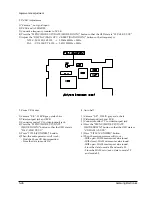
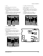
4. Y-FM Deviation Adjustment (Video Block)
Note : You have to do the ÒY-FM Carrier FrequencyÓ
adjustment and the ÒPB Output LevelÓ
adjustment
before you do the Y-FM Deviation adjustment.
Note : It is a little difficult to adjust because you can
check the waveform in playback mode even
though the adjustment is performed in VCR
record mode. When you adjust in record
mode, especially, you can not see the
waveform of playback so that you need to do
it carefully.
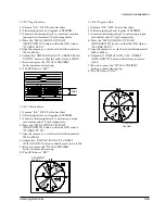
1) Get into the VCR adjustment.
2) Confirm the adjustment mode is 3:DEVIATION in
OSD.
If not, fit the adjustment mode with the MENU
(mode change) button.
3) Connect the camcorder and the Pattern
generator(100% color bar) with A/V cable.
4) Set the camcorder to VCR recording for over 2
minutes with the pattern generator.
5) Connect the oscilloscope to the camcorderÕs video
output.(or Pin #10 of CN502)
6) Rewind the racorded portion you did and press
the play button.
Confirm the waveform of oscilloscope like as
below in playing-back mode.
7) If not OK, you have to do the step 3),4),5) and 6)
after readjustment.
-.In case of the waveform is more than
specification.
Press the C.RESET(data down) button to adjust
to downward the waveform in STOP mode.
Be sure to press the TITLE(confirm) button to
update the setting.
Repeat the step 3),4),5) and 6).
-.In case of the waveform is less than specification.
Press the DISPLAY(data up) button to adjust to
upward the waveform in STOP mode.
Be sure to press the TITLE(confirm) button to
update the setting.
Repeat the step 3),4),5) and 6).
8) If completed, press the MENU(mode change)
button to move to the next adjustment mode.
*. If you want to stop adjustment, do power
resourcing.
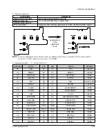
APPROX.
0.7V
APPROX.
0.3V
WHITE ( APPROX. 100% )
H
1.0 0.05Vp-p
5. Record Y Level adjustment (Video Block)
: Record Y Level adjustment is fixed to EVR data
as follows .
-.SCL100 / SCL150 : B9
-.VP-L100/VP-L150 : B5
1) Get into the VCR adjustment.
2) Confirm the adjustment mode is 4:REC Y. in OSD.
If not, fit the adjustment mode with the MENU
(mode change) button.
3) Confirm EPR:B9 in OSD.
4) If not the data, adjust the data to EPR:B9(or B5)
with the DISPLAY (data-up) and the C.RESET
(data-down).
Be sure to press the TITLE(confirm) button to
update the setting.
5) If completed, press the MENU(mode change)
button to move to the next adjustment mode.
*. If you want to stop adjustment, do power
resourcing.
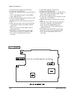
6. PB Outptu Level adjustment.
1) Get into the VCR adjustment.
2) Confirm the adjustment mode is 4:REC Y. in OSD.
If not, fit the adjustment mode with the MENU
(mode change) button.
3) Connect the oscilloscope to the camcorderÕs video
output.(or Pin #10 of CN502)
4) Playback the camcorder with SP mode color bar
tape.
5) Adjust the wave formÕs level like as below with the
DISPLAY(data-up) and the C.RESET(data-down).
Be sure to press the TITLE(confirm) button to
update the setting.
6) If completed, press the MENU(mode change)
button to move to the next adjustment mode.
*. If you want to stop adjustment, do power
resourcing.
Содержание VP-L100
Страница 7: ...Product Specifications 3 4 Samsung Electronics MEMO ...
Страница 21: ...Disassembly and Reassembly 4 14 Samsung Electronics MEMO ...
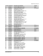
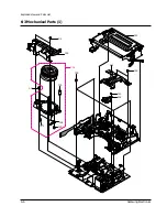
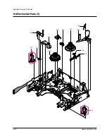
Страница 67: ...Exploded View and Parts List 6 2 Samsung Electronics 6 1 Cabinet Assembly 1 ...
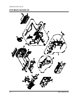
Страница 69: ...Exploded View and Parts List 6 4 Samsung Electronics 6 2 Cabinet Assembly 2 ...
Страница 77: ...Exploded View and Parts List 6 12 Samsung Electronics 6 6 EVF ...
Страница 79: ...Exploded View and Parts List 6 14 Samsung Electronics MEMO ...
Страница 105: ...Block Diagrams 8 2 Samsung Electronics 8 1 Overall Block Diagram Camera ...
Страница 106: ...Block Diagrams Samsung Electronics 8 3 8 2 Overall Block Diagram VCR ...
Страница 107: ...Block Diagrams 8 4 Samsung Electronics 8 3 DC DC Converter ...
Страница 108: ...Block Diagrams Samsung Electronics 8 5 8 4 Drum Servo ...
Страница 109: ...Block Diagrams 8 6 Samsung Electronics 8 5 Capstan Servo ...
Страница 110: ...Block Diagrams Samsung Electronics 8 7 8 6 Video Playback SCL100 150 ...
Страница 111: ...Block Diagrams 8 8 Samsung Electronics 8 7 Video Record SCL100 150 ...
Страница 112: ...Block Diagrams Samsung Electronics 8 9 8 8 Video Playback VP L100 150 ...
Страница 113: ...Block Diagrams 8 10 Samsung Electronics 8 9 Video Record VP L100 150 ...
Страница 114: ...Block Diagrams Samsung Electronics 8 11 8 10 Audio ...
Страница 115: ...Block Diagrams 8 12 Samsung Electronics 8 11 Camera Main ...
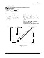
Страница 117: ...PCB Diagrams 9 2 Samsung Electronics 9 1 Main Component Side ...
Страница 118: ...PCB Diagrams Samsung Electronics 9 3 Conductor Side ...
Страница 119: ...PCB Diagrams 9 4 Samsung Electronics 9 2 Rear Component Side Conductor Side ...
Страница 120: ...PCB Diagrams Samsung Electronics 9 5 9 3 Function AE 9 4 Function VCR ...
Страница 121: ...PCB Diagrams 9 6 Samsung Electronics 9 5 Function Menu ...
Страница 123: ...PCB Diagrams 9 8 Samsung Electronics 9 7 CCD Component Side Conductor Side ...
Страница 124: ...PCB Diagrams Samsung Electronics 9 9 9 8 LCD Component Side ...
Страница 125: ...PCB Diagrams 9 10 Samsung Electronics Conductor Side ...
Страница 126: ...PCB Diagrams Samsung Electronics 9 11 Component Side 9 1 MAIN BLUE ...
Страница 127: ...PCB Diagrams 9 12 Samsung Electronics Conductor Side 9 1 MAIN BLUE ...
Страница 128: ...Samsung Electronics 10 1 10 Wiring Diagram ...
Страница 131: ...Schematic Diagrams Samsung Electronics 11 3 11 1 DC DC Converter ...
Страница 132: ...Schematic Diagrams 11 4 Samsung Electronics T T T T T T 1 2 3 4 5 6 11 2 System Control Servo ...
Страница 133: ...Schematic Diagrams Samsung Electronics 11 5 1 2 3 4 5 6 7 8 11 3 Video ...
Страница 134: ...Schematic Diagrams 11 6 Samsung Electronics 11 4 Audio ...
Страница 135: ...Schematic Diagrams Samsung Electronics 11 7 11 5 Front ...
Страница 136: ...Schematic Diagrams 11 8 Samsung Electronics 11 6 Function AE ...
Страница 137: ...Schematic Diagrams Samsung Electronics 11 9 11 7 Function VCR ...
Страница 138: ...Schematic Diagrams 11 10 Samsung Electronics 11 8 Function MENU ...
Страница 139: ...Schematic Diagrams Samsung Electronics 11 11 11 9 Rear ...
Страница 140: ...Schematic Diagrams 11 12 Samsung Electronics 11 10 LCD ...
Страница 141: ...Schematic Diagrams Samsung Electronics 11 13 11 11 CCD 1 2 3 4 5 6 7 8 ...
Страница 142: ...Schematic Diagrams 11 14 Samsung Electronics 11 12 Camera Main 3 2 1 6 7 4 5 8 ...
Страница 143: ...Schematic Diagrams Samsung Electronics 11 15 11 13 EVF ...
Страница 144: ...Schematic Diagrams 11 16 Samsung Electronics 11 14 Adaptor ...


