Reference Information
Samsung Electronics
14-11
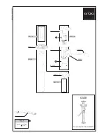
Fig. 14-11
MOTOR LOADING
Œ
BASE DRUM STOPPER
˝
GEAR WHEEL
´
GEAR TENSION
ˇ
POLE BASE S
∏
GEAR CAM MAIN
¨
’
GUIDE RAIL
ˆ
GEAR LOADING S
Ø
GEAR LOADING T
”
POLE BASE T
14-1-3-8 Pole Base S, T
1) Motor Loading
Œ
rotates.
2) Gear Wheel
´
rotates.
3) Gear Tension
ˇ
rotates.
4) Gear Cam Main
¨
rotates.
5) Gear Loading S
ˆ
, T
Ø
rotates.
6) Pole Base S
∏
, T
”
slide along Guide Rail
’
.
7) Pole Base S
∏
, T
”
attach to Base Drum Stopper
˝
.
Mode
Pole Base S, T
OFF ON
EJECT
UNLOAD
LD 1
LD 2
STOP
PLAY
Содержание VP-D451
Страница 10: ...Product Specification 2 4 Samsung Electronics MEMO ...
Страница 30: ...3 20 Alignment and Adjustments Samsung Electronics MEMO ...
Страница 46: ...4 16 Disassembly and Reassembly Samsung Electronics MEMO ...
Страница 66: ...Exploded View and Parts List 5 20 Samsung Electronics MEMO ...
Страница 83: ...Samsung Electronics 8 1 8 Wiring Diagram MEMORY STICK VP D453 I D6620I VP D454 I D455 I D6650I ...
Страница 84: ...Wiring Diagram 8 2 Samsung Electronics MEMO ...
Страница 86: ...PCB Diagrams 9 2 Samsung Electronics 9 1 Main PCB COMPONENT SIDE ...
Страница 87: ...PCB Diagrams Samsung Electronics 9 3 L708 Œ ˇ ˆ L704 L706 L717 L719 ...
Страница 88: ...PCB Diagrams 9 4 Samsung Electronics CONDUCTOR SIDE Fuse 1 25A 32V ...
Страница 94: ...PCB Diagrams 9 10 Samsung Electronics MEMO ...
Страница 114: ...Schematic Diagrams 10 20 Samsung Electronics This Document can not be used without Samsung s authorization MEMO ...
Страница 128: ...Troubleshooting 12 8 Samsung Electronics MEMO ...
Страница 140: ...Circuit Operating Description 13 12 Samsung Electronics MEMO ...
Страница 184: ...Reference Information 14 44 Samsung Electronics MEMO ...