


2-4
Samsung Electronics
Alignment and Adjustment
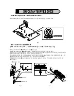
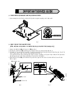
2-3 Head Switching Point Adjustment
1) Playback the alignment tape.
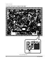
2) Press the “SW718 (TEST)” button on Main PCB to set the adjustment mode. (See Fig. 2-2)
3) Press the “SPEED” button of remote control then adjustment is operated automatically. (See Fig. 2-1)
4) Turn the Power off.
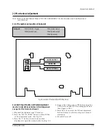
2-4 NVRAM Option Setting
1) Press the “SW718 (TEST)” button on Main PCB to set the adjustment mode. (See Fig. 2-2)
2) Press the “MENU” button on the remote control about 5 seconds then option setting display is appeared.
(See Fig. 2-4)
3) Select the option number (See Table 2-1) of corresponding model with “FF” and “REW” button on the
remote control.
4) If selecting the option number is completed, press the “PLAY” button of remote control.
(If “PLAY” button is pressed, the selected number is changes reversed color. ; See Fig. 2-4)
5) Press the “OK” button of remote control again to store the option number.
(“PLEASE WAIT” is displayed for a second as shown Fig. 2-5 and this setting is completed.)
6) Turn the Power off.
1) NVRAM Option is adjusted at production line basically.
2) In case Micom (IC601) and NVRAM (IC605 ; EEPROM) is replaced, be sure to set the corresponding option number of the repaired
model. (If the option is not set, the unit is not operated.)
01
02
03 04
05
06 07
08
09 10 11 12 13 14 15 16
17 18 19 20 21 22 23 24
25 26 27 28 29 30 31 32
33 34 35 36 37 38 39 40
41 42 43 44 45 46 47 48
**
OPTION DIODE
**
CNG : SAVE : OK
Fig. 2-4
01
02
03 04
05
06 07
08
09 10 11 12 13 14 15 16
17 18 19 20 21 22 23 24
25 26 27 28 29 30 31 32
33 34 35 36 37 38 39 40
41 42 43 44 45 46 47 48
**
OPTION DIODE
**
CNG : SAVE : OK
PLEASE WAIT
Fig. 2-5
MODELS
OPTION NUMBER
SVR-639
2, 6, 8, 11, 12, 13, 16, 18, 19, 20, 21, 22, 25, 30, 31, 32, 33, 37, 41, 44, 46, 50, 54
SVR-633
6, 8, 11, 12, 13, 17, 18, 22, 25, 30, 31, 32, 35, 41, 42, 44, 45, 46, 50, 54
SVR-630
8, 11, 12, 13, 17, 18, 22, 25, 30, 31, 32, 35, 37, 38, 41, 42, 46, 50, 54
SVR-537
9, 10, 11, 13, 17, 18, 20, 22, 30, 31, 32, 34, 39, 40, 42, 45
<Table 2-1>
Содержание SVR-537
Страница 17: ...Exploded View and Parts List 3 8 Samsung Electronics MEMO ...
Страница 26: ...Schematic Diagrams Samsung Electronics 5 3 5 1 S M P S ...
Страница 27: ...Schematic Diagrams 5 4 Samsung Electronics 5 2 Power Drive ...
Страница 29: ...Schematic Diagrams 5 6 Samsung Electronics 5 4 Audio Video ...
Страница 30: ...Schematic Diagrams Samsung Electronics 5 7 5 5 Hi Fi ...
Страница 31: ...Schematic Diagrams 5 8 Samsung Electronics 5 6 RF VCP ...
Страница 32: ...Schematic Diagrams Samsung Electronics 5 9 5 7 SECAM SVR 639 Only ...
Страница 33: ...Schematic Diagrams 5 10 Samsung Electronics 5 8 Input Output 1 Scarrt Jack SVR 639 Only ...
Страница 34: ...Schematic Diagrams Samsung Electronics 5 11 5 9 Input Output RCA Jack ...
Страница 35: ...Schematic Diagrams 5 12 Samsung Electronics 5 10 OSD ...
Страница 36: ...Schematic Diagrams Samsung Electronics 5 13 5 11 VFD Display SVR 639 ...
Страница 37: ...Schematic Diagrams 5 14 Samsung Electronics 5 12 LED Module Display SVR 633 SVR 630 ...
Страница 38: ...Schematic Diagrams Samsung Electronics 5 15 5 13 LED Single Display SVR 537 ...
Страница 40: ...Schematic Diagrams Samsung Electronics 5 17 5 15 Remote Control Multi TV ...
Страница 41: ...Schematic Diagrams 5 18 Samsung Electronics 5 16 Remote Control VCR Only ...
Страница 66: ...2 6 Samsung Electronics Alignment and Adjustment MEMO ...


