


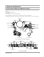


Alignment and Adjustment
Samsung Electronics
2-5
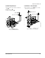
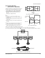
4) As rotating Disk S Reel
Œ
clockwise and the
region of adjusting in the Main Base (in shape of
slit) clockwise or counterclockwise after inserting
screw driver in the slit on Main Base. Adjust the
left end edge of Lever Tension AssÕy
ˇ
to 1.3
+1.5/-0.5mm from the location of mark in the
Main Base.
5) As rotating Disk S Reel
Œ
, double-check the loca-
tion of the left end edge of Lever Tension AssÕy
and the quantity of crossing from mark on Main
Base. (+1.0/-0.5mm)
Counterclockwise
: Torque UP
Clockwise
: Torque DOWN
Back Tension should be 56 ± 15g.cm at inspecting it
with Back Tension Meter.
1.0mm
0.5mm
ˇ
LEVER TENSION ASS'Y
Œ
DISK S REEL
´
ADJUSTING
ADJUSTING SLIT
1.3
Fig. 2-13 Tension Pole and Back Tension Adjustment
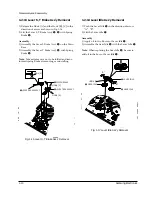
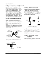
1) Remove the holder cassette assÕy and then push
the lever FL Arm-R to the direction of loading.
2) Push the lever tension drive
Œ
in the direction of
arrow. (See Fig. 2-11)
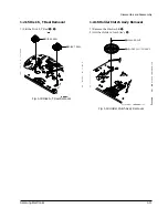
3) Turn the gear worm wheel
´
clockwise so that
ÒTiming PointÓ of the slider FL drive
ˇ
and gear
FL cam
¨
can be aligned (See Fig. 2-12)
Fig. 2-11
Fig. 2-12
¨
GEAR FL CAM
´
GEAR WORM WHEEL
ˇ
SLIDER FL DRIVE
P
TIMING POINT
Œ
LEVER TENSION DRIVE
LEVER TENSION
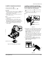
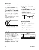
Note
:
1) Mark on Main Base is located in about 1.3mm
from inside of bending line.
2) Be careful not to deform the region of adjusting on
Main Base up and down at adjusting.
2-4 Location adjustment and Confirmation of Tension Post
Содержание SVR-537
Страница 17: ...Exploded View and Parts List 3 8 Samsung Electronics MEMO ...
Страница 26: ...Schematic Diagrams Samsung Electronics 5 3 5 1 S M P S ...
Страница 27: ...Schematic Diagrams 5 4 Samsung Electronics 5 2 Power Drive ...
Страница 29: ...Schematic Diagrams 5 6 Samsung Electronics 5 4 Audio Video ...
Страница 30: ...Schematic Diagrams Samsung Electronics 5 7 5 5 Hi Fi ...
Страница 31: ...Schematic Diagrams 5 8 Samsung Electronics 5 6 RF VCP ...
Страница 32: ...Schematic Diagrams Samsung Electronics 5 9 5 7 SECAM SVR 639 Only ...
Страница 33: ...Schematic Diagrams 5 10 Samsung Electronics 5 8 Input Output 1 Scarrt Jack SVR 639 Only ...
Страница 34: ...Schematic Diagrams Samsung Electronics 5 11 5 9 Input Output RCA Jack ...
Страница 35: ...Schematic Diagrams 5 12 Samsung Electronics 5 10 OSD ...
Страница 36: ...Schematic Diagrams Samsung Electronics 5 13 5 11 VFD Display SVR 639 ...
Страница 37: ...Schematic Diagrams 5 14 Samsung Electronics 5 12 LED Module Display SVR 633 SVR 630 ...
Страница 38: ...Schematic Diagrams Samsung Electronics 5 15 5 13 LED Single Display SVR 537 ...
Страница 40: ...Schematic Diagrams Samsung Electronics 5 17 5 15 Remote Control Multi TV ...
Страница 41: ...Schematic Diagrams 5 18 Samsung Electronics 5 16 Remote Control VCR Only ...
Страница 66: ...2 6 Samsung Electronics Alignment and Adjustment MEMO ...


