UTP Power Supply Hub
User Guide
6
UTP Power Supply Hub
User Guide
7
RJ-45 Connector Wiring Chart for Video Input (Camera
↔
SPU-400)
RJ-45 Connector Wiring Chart for Video Output (SPU-400
↔
Receiver)
RJ-45 Connector Wiring Chart for Data Input (SPU-400
↔
Controller)
No.
Color
Function
1
White
Video
2
Orange
Video Output -
3
Green + White
RS-485 TX +
4
Blue
AC Power -
5
Blue + White
AC Power +
6
Green
RS-485 TX -
7
Brown + White
AC Power +
8
Brown
AC Power -
No.
Color
Function
1
White
Camera 2, (+)
2
Orange
Camera 2, (-)
3
Green + White
Camera 3, (+)
4
Blue
Camera 1, (-)
5
Blue + White
Camera 1, (+)
6
Green
Camera 3, (-)
7
Brown + White
Camera 4, (+)
8
Brown
Camera 4, (-)
No.
Color
Function
1
White
RS-485 2, (+)
2
Orange
RS-485 2, (-)
3
Green + White
RS-485 3, (+)
4
Blue
RS-485 1, (-)
5
Blue + White
RS-485 1, (+)
6
Green
RS-485 3, (-)
7
Brown + White
RS-485 4, (+)
8
Brown
RS-485 4, (-)
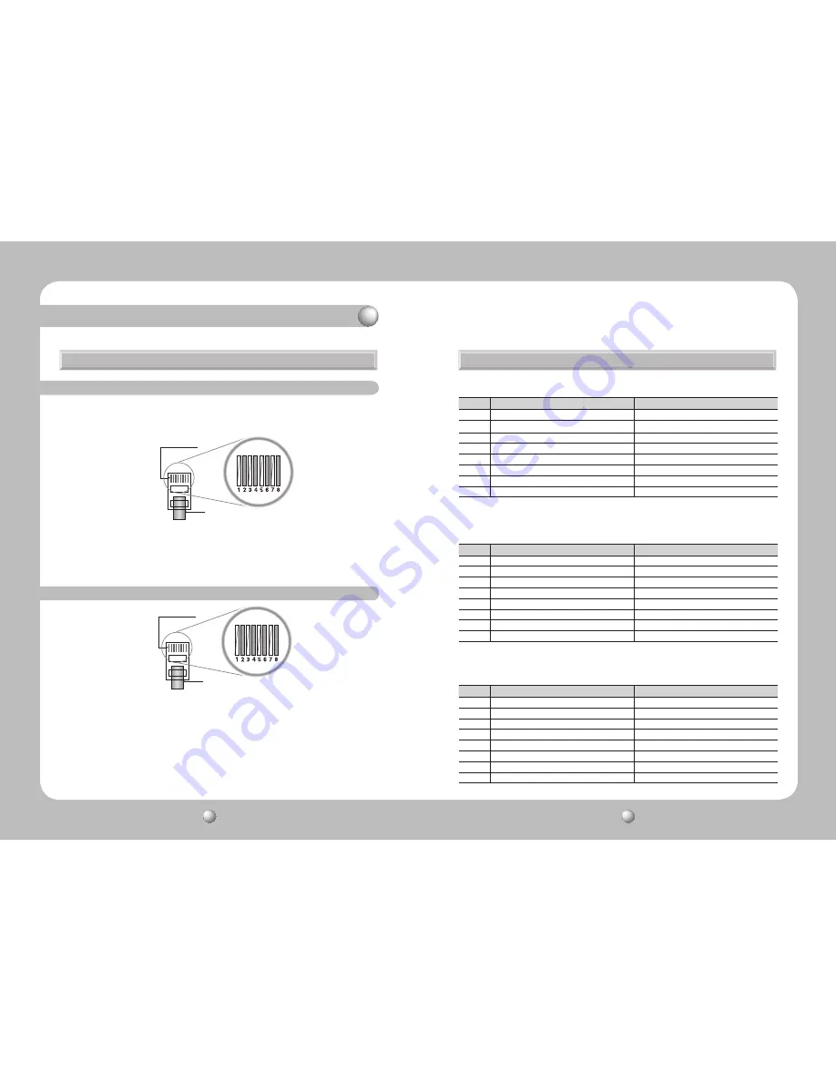
3-2. Installing the SPU-400 and Connecting UTP Cable
3-3. SPU-400 Connector Wiring Chart
3-2-2. Receiver-Side UTP Cable
①
Connect an RJ-45 Plug to a camera UTP cable.
• The following pin alignment complies with the communication cable standards and is
provided for your convenient installation.
①
Connect the RJ-45 plugs to the CH1 to 4 ports on the SPU-400.
②
Connect RS-485 data cables according to the signals: positive and negative. (For
RS-485 data.)
③
This equipment is indoor use and all the communication wirings are limited to
inside of the building
①
Connect an RJ-45 Plug to a Receiver UTP cable.
②
Connect an RJ-45 plug to a Receiver connector on the SPU-400.
③
Connect the AC power plug to the AC Inlet on the SPU-400.
④
Double check the UTP connections, and then turn on the power switch on the back side.
The camera starts operating as the front LED turns green.
⑤
At the Receiver end, check the video signaling status.
⑥
This equipment is indoor use and all the communication wirings are limited to inside of
the building
Copper Connector
UTP Coating
Copper Connector
UTP Coating
3-2-1. Camera-Side UTP Cable
3. Product Parts and Peripheral Device Connection


