


COLOR CCD CAMERA
User’s Manual
16
COLOR CCD CAMERA
User’s Manual
17
Installation Procedures
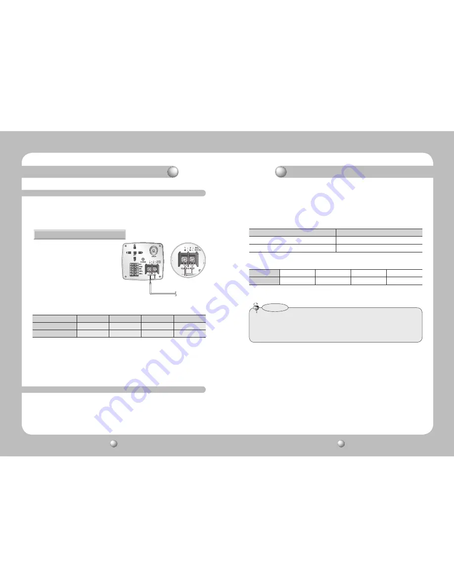
Connecting to Power
Control via RS-485 Interface
Since power specifications differ depending on the model, make sure to check your
model name and specifications before connecting power.
You can connect power as shown in the following figure.
For AC / DC power
• Since the power specification supports
both AC and DC, connect AC 24V,
500mA Adaptor or DC 12V, 500mA
Adaptor.
• As shown in the table above, voltage decreases as the wire gets longer.
Therefore use of an excessively long adaptor output line for connection to the
camera may affect the performance of the camera.
…
Standard voltage for camera operation : DC 12V±10%, AC 24V±10%
…
There may be some deviation in voltage drop depending on the type of wire and the manufacturer.
When the resistance value of copper wire is at [20°C(68°F)]
Copper wire size (AWG)
#24(0.22mm
2
)
#22(0.33mm
2
)
#20(0.52mm
2
)
#18(0.83mm
2
)
Resistance (Ω/m)
0.078
0.050
0.030
0.018
Voltage Drop (V/m)
0.028
0.018
0.011
0.006
RS-485 converter.
Example) PC Serial Port (COM1)
→
Serial Cable
→
RS-485 Converter
→
Camera
RS-485 Control Port
The camera can be controlled by using external controllers like a Remote controller.
(RS-485 Communication)
(1) To control by PC
Connect the RS-485 control port of the camera and the serial cable through an
* RS-485 Communication establishment initial value
• To control the camera by constructing an additional controller, use Pelco-D protocol or
STW protocol (Samsung Techwin protocol).
• You can use System Controller such as SCC-101 or SCC-3100A through RS-485
communication.
Notes
485 Control Board Connection Port
RS-485 Control Port
(+) CONNECTION TERMINAL (TRX+)
485+
(
-
) CONNECTION TERMINAL (TRX-)
485-
Item
Camera ID
BAUD RATE
UART MODE
RET PKT
Initial value
1
9600
8-NONE-1
ENABLE
Installation Procedures


