


System Overview
Samsung Electronics
Service Manual
3-1
3
3
3. System Overview
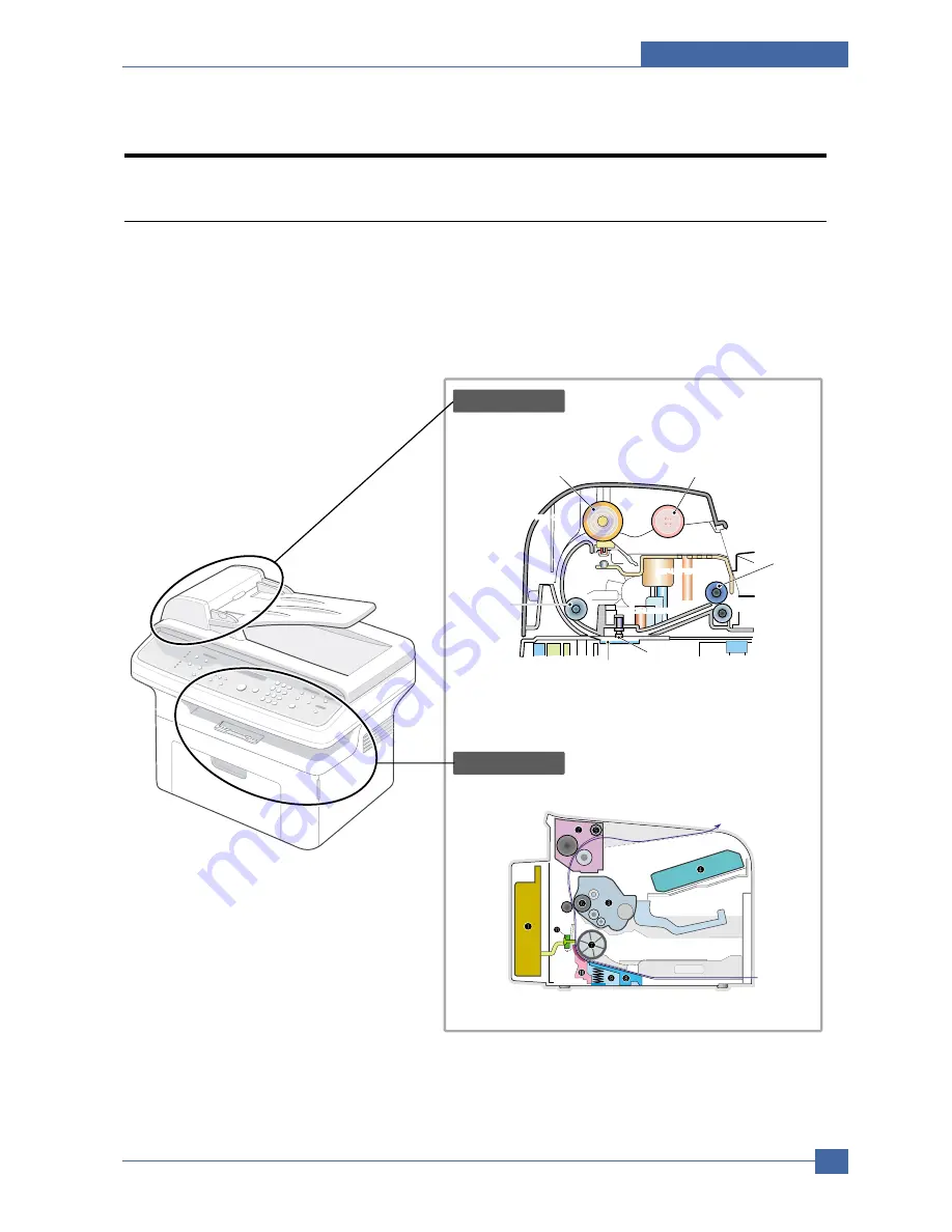
3.1 System Layout
The SCX-4521F/4321 is roughly made up Main Control part, Operation Panel part, Scanner part, Line
Interface part and Power part. Each Part is separated Module which focus on common and standard design
of different kind products. main control part adopting Fax & LBP Printer exclusive Controller is chorus2
CPU(ASIC) and 1 Board. Scanner part is composed of ADF and Platen and is connected with Main by
Harness.
ADF ROLLER
Scanner part
Engine Part
ADF-UPPER
PICK-UP ROLLER
EXIT ROLER
WHITE BAR
ADF-GLASS
FEED ROLLER
SCAN UPPER
SCAN UPPER
SCAN UPPER
ADF-LOWER
COVER OPEN
BIN PATH
Содержание SCX-4321
Страница 47: ...Samsung Electronics Service Manual Alignment and Adjustments 4 15 ...
Страница 127: ...Exploded Views Parts List Samsung Electronics Service Manual 7 9 7 8 MP Tray Assembly Exploded Views 0 1 2 3 4 5 ...
Страница 140: ...Block diagram Service Manual 8 2 Samsung Electronics 8 8 8 Block Diagram 8 1 System Block Diagram ...


