background image

INDOOR UNIT

SC07AS2
SC07AS2A
SC09AS2
SC12AS4

OUTDOOR UNIT

SC07AS2X
SC07AS2AX
SC09AS2X
SC12AS4X

SERVICE

Manual

CONTENTS

AIR CONDITIONER

1

1. Product Specifications

1

2. Operating Instructions

1

3. Disassembly and Reassembly

1

4. Refrigerating Cycle Diagram

1

5. Set Up the Model Option

1

6. Troubleshooting

1

7. Exploded Views and Parts List

1

8. Block Diagram

1

9. PCB Diagram

10. Wiring Diagram

11. Schematic Diagram

ROOM AIR CONDITIONER

 DB98_16999A(2)_co  04/3/12 10:22 AM  Page 3

Содержание SC07AS2

Страница 1: ...CONTENTS AIR CONDITIONER 11 Product Specifications 12 Operating Instructions 13 Disassembly and Reassembly 14 Refrigerating Cycle Diagram 15 Set Up the Model Option 16 Troubleshooting 17 Exploded Vie...

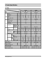
Страница 2: ...st Condition Maximum Operation Condition Indoor unit Outdoor unit Wall mounted 2 30 0 9 6 2 22 36 50 2 95 1 220 240 50 780 3 5 96 9 17 0 250V 10 16A 795 x 258 x 179 660 x 495 x 235 31 3 x 10 2 x 7 0 2...

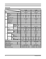
Страница 3: ...ximum Operation Condition Indoor unit Outdoor unit Wall mounted 2 70 1 4 6 8 22 39 51 2 87 1 220 240 50 940 4 2 97 3 21 0 250V 10 16A 795 x 258 x 179 660 x 495 x 235 31 3 x 10 2 x 7 0 26 0 x 19 5 x 9...

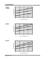
Страница 4: ...3 Samsung Electronics 1 2 Pressure Graph SC07AS2 SC07AS2A SC09AS2 SC12AS4...

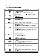
Страница 5: ...and run the air conditioner or On Off timer set up Turbo Sleep mode selection button Press the button one or more times until appears The air conditioner cools or heats the room as quickly as possibl...

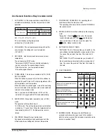
Страница 6: ...FAN SPEED Manual 3 step Auto 4 step Fan speed automatically varies depending on both the difference between setting and the room temperature 7 COMPULSORY OPERATION For operating the air conditioner w...

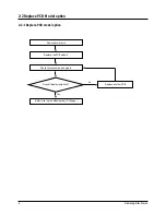
Страница 7: ...eplace PCB Model option 2 2 1 Replace PCB model option No Yes Remove power cord Replace the PCB module Check the connection and plug in Refer to set up the Model option 13 15page Replace another PCB D...

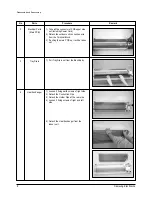
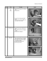
Страница 8: ...ide the lower Front Grille down then disassemble it by pulling it forwards 5 Take the left and right Filter out 6 Loosen one of the right screw and detach the Terminal Cover 7 Detach the thermistor fr...

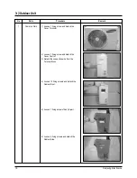
Страница 9: ...ding Power Cord 2 Detach the outdoor unit connection wire from the Terminal Block 3 If pulling the main PCB up it will be taken out 1 Pull Tray Drain out from the Back Body 1 Loosen 2 fixing earth scr...

Страница 10: ...ssembly No Parts Procedure Remark 5 Fan Motor Cross Fan 1 Loosen 2 fixing screws and detach the Motor Holder 2 Loosen 1 screw of Fan Motor By use of M3 wrench 3 Detach the Fan Motor from the Fan 4 Det...

Страница 11: ...ing screw and detach the Cover Terminal 2 Loosen 1 fixing screw and detach the Cover Control 3 Detach the connection wire from the Terminal Block 4 Loosen 13 fixing screws and detach the Cabinet Front...

Страница 12: ...etach the Motor 4 Loosen 5 fixing screws and detach the Motor Bracket from the Base 1 Loosen 2 fixing screws of left and right side 2 Disassemble the inlet and outlet pipe by welding 3 Detach the Heat...

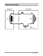
Страница 13: ...xchanger Evaporator Gas side 3 Way valve 2 Way valve Liquid side Capillary tube Gas leak check point Cross Fan Heat Exchanger Condenser Propeller Fan Compressor T1 T2 Cooling 4 Refrigerating Cycle Dia...

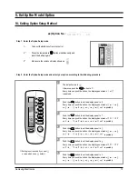
Страница 14: ...h the button the display panel reads or repeatedly Push the button to set the display panel to Every time you push the button the display panel reads repeatedly Setting is not required if you must a v...

Страница 15: ...n key to set the display part to and check the display part The display part shows Press the Mode Selection key to set the display part to and check the display part The display part shows Step 4 Pres...

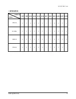
Страница 16: ...Model Option OPTION ITEMS REMOCON MODEL SEG1 SEG2 SEG3 SEG4 SEG5 SEG6 SEG7 SEG8 SEG9 SEG10 SEG11 SEG12 SC07AS2 SC07AS2A SC09AS2 0 2 0 0 0 0 1 7 A 0 F b 0 2 0 0 0 0 1 7 A 0 F b 0 2 0 0 0 0 1 7 A 2 2 E...

Страница 17: ...The compressor and indoor fan stop intermittently in HEAT mode In case of heat pump model Indoor fan and outdoor fan stop operation intermittently in a HEAT mode 1 2 3 4 5 6 7 8 9 Operation of air con...

Страница 18: ...R TURBO Lamp flickering Lamp off No response from the remote control operation signal Unable to operate the outdoor unit Plug out and plug in 5 seconds later Press the TURBO button with the remote con...

Страница 19: ...e air conditioner Check whether two wires of power cord are connected correctly to the terminal block and control board Check whether the fuse on the control board is normal FUSE 3 15 A 250 V Check th...

Страница 20: ...PCB CN43 connector and measure the sensor resistance with an ohmmeter tester Connect the sensor to CN43 supply power and measure the voltage of 1 and 2 of the CN43 connector MICOM Error or Connector...

Страница 21: ...or 3 Assemble the room pipe sensor to PCB plug in and check the voltage of connector 3 and 4 If the resistance is below 0 5V or over 4 9V replace the indoor Main PCB short or disconnected in the PCB b...

Страница 22: ...5 seconds Does the OPERATION lamp blink Does the Solid State Relay SS71 work properly Is the supply voltage of the fan motor sufficient Test rod location PCB CN72 Condition About AC 180V Normal voltag...

Страница 23: ...ng out the power cord should be reconnected within 5 seconds Does the OPERATION lamp blink Yes No Yes No No No Yes Yes Outdoor unit is out of order Power relay is out of order Power relay should be re...

Страница 24: ...start when swing button of the remote control unit pushed Voltage at pin 57 60 of micom IC04 change Squarewave Voltage at pin 2 5 of CN61 motor connector change Squarewave UP DOWN louver motor is fau...

Страница 25: ...eck the voltage of No 3 and No 2 of the main PCB CN91 while operating the remote control When the voltage descends below 3V the assembly module PCB is normal and the main PCB is poor Then replace the...

Страница 26: ...MEMO 25 Samsung Electronics...

Страница 27: ...1 3 1 4 14 2 14 5 14 4 14 6 2 10 4 1 6 2 11 14 1 2 3 1 1 1 1 5 1 6 1 7 3 7 8 15 12 6 6 1 You can search for the updated part code number through the ITSELF URL http itself sec samsung co kr 7 Explode...

Страница 28: ...Y REMOCON ASS Y 1 1 1 6 DB94 00547A ASS Y BACK BODY ASS Y 1 DB94 00508A ASS Y BACK BODY ASS Y 1 1 6 1 DB61 01779A BACK BODY HIPS 1 DB61 01780A BACK BODY HIPS 1 1 6 2 DB94 00258A ASS Y BEARING ASS Y 1...

Страница 29: ...Samsung Electronics 28 7 2 Outdoor Unit 12 15 1 15 2 4 2 14 5 15 6 18 19 9 2 11 22 10 21 15 5 20 4 1 7 6 23 8 3 1 17 16 4 13 15 3 15 15 4 24...

Страница 30: ...ASS Y PARTITION ASS Y 1 1 DB94 00497A ASS Y PARTITION ASS Y 1 DB94 00520B ASS Y PARTITION ASS Y 1 15 DB93 02688B ASS Y CONTROL OUT ASS Y 1 DB93 02688F ASS Y CONTROL OUT ASS Y 1 DB93 02688A ASS Y CONT...

Страница 31: ...Samsung Electronics 30 7 3 Ass y Control In Indoor Unit SC07AS2 SC07AS2A SC09AS2 DB93 02524B...

Страница 32: ...01630A CASE CONTROL ASS Y MAIN PCB ASS Y TERMINAL BLOCK ASS Y SUB PCB PLATE TERMINAL LOW HOLDER WIRE CLAMP SCREW MACHINE SCREW MACHINE SCREW MACHINE ASS Y C W SUB ASS Y C W STEP MOTOR ASS Y THERMISTOR...

Страница 33: ...Samsung Electronics 32 Exploded Views and Parts List SC12AS4 DB93 02539B...

Страница 34: ...ASE CONTROL ASS Y MAIN PCB ASS Y TERMINAL BLOCK ASS Y SUB PCB PLATE TERMINAL LOW HOLDER WIRE CLAMP SCREW MACHINE SCREW MACHINE SCREW MACHINE ASS Y C W SUB ASS Y C W STEP MOTOR ASS Y THERMISTOR HOLDER...

Страница 35: ...ON SLEEP SELECT MODE AUTO COOL DRY FAN FAN SPEED SELECT H M L BLADE H MOVING SELECT ON OFF TIMER SELECT FUNCTION SELECT TEMPERATURE SELECT ZERO VOLTAGE DETECT BLADE CONTROL AUTO GRILLE CONTROL INDOOR...

Страница 36: ...35 Samsung Electronics 9 PCB Diagram 9 1 ASS Y MAIN PCB 7K 9K 12K DB93 02447B TOP...

Страница 37: ...Samsung Electronics 36 PCB Diagram BOTTOM...

Страница 38: ...C 4 6 1 IC01 IC PWM CONTROLLER 255 DIP 8P 300MIL PLASTIC 0 3 700V 40TO 150C 1 530mA ST NTC1 THERMISTOR NTC 22ohm 1 4A 3100K 9 5mW C 7 0 1 VA71 VARISTOR 560V 2500A 17 5x7 5mm TP 1 R609 R CHIP 560ohm 5...

Страница 39: ...0mohm 1 F702 FUSE CARTRIDGE 250V 3 15A TIME LAG GLASS 5x20mm 1 CN71 CONNECTOR HEADER 1WALL 3P 1R 7 92mm STRAIGHT SN BLU 1 CN72 CONNECTOR HEADER 1WALL 3P 1R 7 92mm STRAIGHT SN WHT 1 CN91 CONNECTOR HEAD...

Страница 40: ...08 WHT 1 SNA 4 LED LAMP GRN SM3517 2 SNA 5 LED LAMP ORG SO3517 1 SNA 6 RESISTOR 470ohm 1 2W 1 SNA 7 MODULE REMOCON FRP4021H10 1 SNA 8 DIODE 1N4148 1 SNA 9 C CERAMIC 1nF 50V 1 SNA 10 C CERAMIC 100nF 50...

Страница 41: ...Samsung Electronics 40 10 Wiring Diagram 10 1 Indoor Unit 7K 9K 12K This Document can not be used without Samsung s authorization Code No DB98 16252A...

Страница 42: ...amsung Electronics This Document can not be used without Samsung s authorization 10 2 Outdoor Unit 7K 9K 12K Code No DB98 15721A C1 MOTOR CAPACITOR FM FAN MOTOR C2 COMP CAPACITOR O L P OVER LOAD PROTE...

Страница 43: ...Samsung Electronics 42 11 Schematic Diagram 11 1 Indoor Unit 7K 9K 12K This Document can not be used without Samsung s authorization...

Страница 44: ...MEMO 43 Samsung Electronics...

Страница 45: ...MEMO Samsung Electronics 44...

Страница 46: ...Manual is a property of Samsung Electronics Co Ltd Any unauthorized use of Manual can be punished under applicable International and or domestic law Samsung Electronics Co Ltd Mar 2004 Printed in Kor...

Отзывы: