background image

Firmware update

6-4 

Copyright© 1995-2012 SAMSUNG. All rights reserved.

6-3 Upgrade

 How to execute the firmware

  The firmware is configured in the following structure. 

  Code area is where the execution codes to operate the camera are located, and the Partition [1:3] area is where the various resources 

  necessary to operate the camera are saved. Among these areas, Partition 3 area is where the Defective Pixel adjustment data and 

  Lens Shading adjustment data are saved. 

  User Area is where the setting values are saved through the menu when the user uses the camera, and the adjusted data through 

  integrated process is saved. 

► Reference of general version:


  - As the version to update the Code + Partition [1:2] area, this protects both the adjusted data saved in the User Area and 

    the Partition 3 area.

1. Insert the memory card containing the firmware data file and Upgrade Script file into the camera.

  * You need two files to upgrade the firmware and the required files are firmware data file and Upgrade Script file.

  * Because all data saved on the FLASH memory will be reset when you upgrade the firmware, back up 

    your data before proceeding with the upgrade.


2. Use the AC adaptor or fully charged batteries for the power. 


  * You can proceed with the upgrade only when the battery level is full (Icon showing full up to 3rd level). 

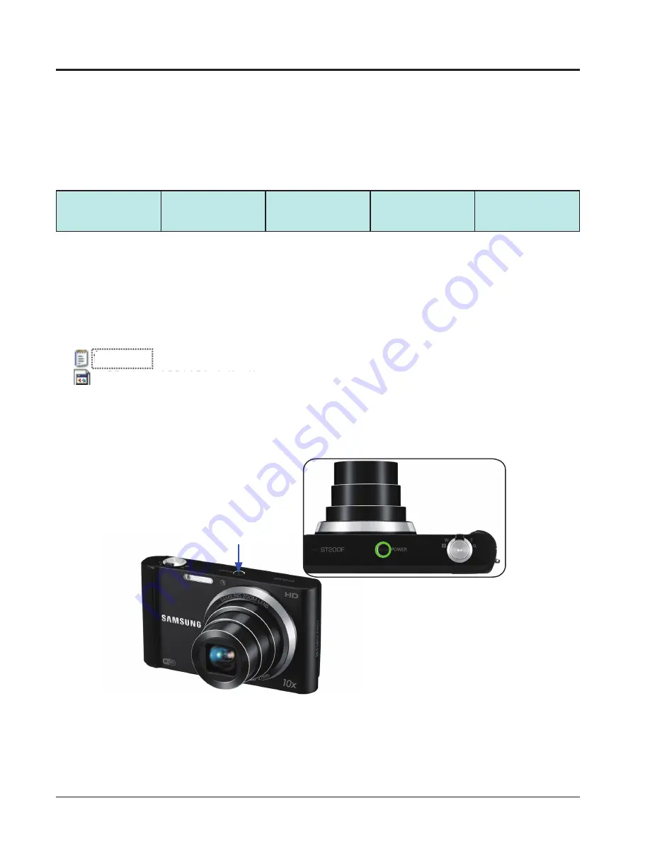
3. Turn on the power of the camera.

Code

partition1

partition2

partition3

User Area

<Table. 6-1>

Fig. 6-6

Power ON

ST200-DSP-1201194-full.elf

fwup.txt

Содержание SAMSUNG ST200F

Страница 1: ...NTS SAMSUNG ST200 ST200F DIGITAL CAMERA SERVICE Manual 1 Repair information 2 Product specifications 3 Disassembly and reassembly 4 PCB diagrams 5 Block diagram 6 Firmware update 7 Adjustment 8 Exploded view and parts list ...

Страница 2: ...tions 2 1 Specifications 2 1 2 2 Product comparison 2 2 2 3 Accessories information 2 3 2 4 About the memory card 2 5 2 5 About the battery 2 6 3 Disassembly and reassembly 3 1 Screw parts list 3 1 3 2 Disassembly of main unit 3 2 3 3 Disassembly of barrel 3 11 3 4 Reassembly of barrel 3 18 4 PCB diagrams 4 1 MAIN PCB 4 1 4 2 TOP PCB 4 2 4 3 CCD FPCB 4 2 4 4 CAP FPCB 4 3 5 Block diagram ...

Страница 3: ...7 3 Shutter close time ADJ 7 4 7 4 Flash ADJ 7 5 7 5 Punt ADJ 7 6 7 6 Vertical line ADJ 7 8 7 7 CCD defect ADJ 7 9 7 8 OIS centering ADJ 7 9 7 9 Serial number writing process 7 10 8 Exploded view and parts list 8 1 BODY ASSEMBLY 8 1 8 2 CHAMBER ASSEMBLY 8 3 8 3 FRONT COVER ASSEMBLY 8 4 8 4 BACK COVER ASSEMBLY 8 6 8 5 BARREL ASSEMBLY 8 7 8 6 PACKING ITEMS 8 11 ...

Страница 4: ...ndards of customer satisfaction and service 1 General terms and conditions It is guaranteed to be free of charge from defects in material and workmanship under normal use for a period of one year from date of purchase Digital Camera and lens come with a one year limited warranty from the date of purchase The duration of the warranty depends on the laws in the country in which it was purchased The ...

Страница 5: ...available for service repair company has the right to provide warranty The warranty does not affect the consumers rights against the company related to its information For the length of the period indicated on the chart below it starts with the date of original purchase Part Name Warranty Period Battery Charger Six months AC Adaptor Battery Remote Control CD Software Three months Earphone Pouch fo...

Страница 6: ... natural disasters Replacement charge Repair charge and replace the prod uct at the cost of the depreciated value 4 Repair Claims 1 Repair free of charge Essentially the following causes of damage are covered a Failing to function properly under normal use during the limited warranty period b Repair Services free of charge is granted for the performance of a specific contract 2 Repair charges This...

Страница 7: ... static handing procedures included with the anti static mat to ensure that there is no electrostatic discharge and component damage 2 Static electricity is the biggest danger to the PCB parts you are about to disassemble or assemble It s important to use your anti static wrist strap to prevent damage to these components 3 Dismantling a discrete electronic component such as main capacitor is dange...

Страница 8: ...00 sec Night Shot 8 1 2 000 sec Flash Range Wide 0 3 m 3 6 m ISO Auto Tele 0 5 m 2 0 m ISO Auto ISO Range Auto ISO 80 ISO 100 ISO 200 ISO 400 ISO 800 ISO 1600 ISO 3200 Focal Length Samsung 10X Zoom Lens f 4 85 48 5mm 35mm film equivalent 27 270 mm Storage Internal memory Approx 16 MB External memory Optional microSD card up to 2 GB guaranteed microSDHC card up to 32 GB guaranteed microSDXC card up...

Страница 9: ... 8 1 2 000 sec Smart Auto 8 1 2 000 sec Program 1 1 2 000 sec Night 8 1 2 000 sec ISO Range Auto ISO 80 ISO 100 ISO 200 ISO 400 ISO 800 ISO 1600 ISO 3200 Auto ISO 80 ISO 100 ISO 200 ISO 400 ISO 800 ISO 1600 ISO 3200 Focal Length Samsung 10X Zoom Lens f 4 85 48 5mm 35mm film equivalent 27 270 mm Samsung Lens f 4 5 22 5 mm 35 mm film equivalent 25 125 mm Storage Internal memory Approx 16 MB External...

Страница 10: ...0182A AD5055_AUS AD44 00185A AD5055_ARG AD44 00181A AD5055_BRA AD44 00180A AD5055_CHI AD44 00184A USB cable CHI AD39 00190A EXP AD39 00191A Battery AD43 00199A Strap BLACK AD63 02604A SILVER AD63 02596A DV300 DV300F DV305 DV305F User Manual CD ROM AD46 00433A Quick Start Guide ST200F_EUR1 AD68 06850A ST200F_EUR2 AD68 06851A ST200F_EUR3 AD68 06852A ST200F_ASIA AD68 06853A ST200F_S CHI AD68 06849A S...

Страница 11: ...l items information image Description Parts No Optional items Camera case CC9S70B AD69 03284A CC9S71N AD69 03285A CC9S30B AD69 03283A CC9U21B P AD69 02964A AD69 03010A CC9U11B AD69 02397B A V cable AD39 00191A Battery charger AD44 00176A Memory card 2G 1109 001446 4G 1109 001420 8G 1109 001418 ...

Страница 12: ...ry capacity may differ depending on shooting scenes or shooting conditions These capacities are based on a 1 GB microSD card Size Super Fine Fine Normal P h o t o s 4608 X 3456 105 206 303 4608 X 3072 117 230 337 4608 X 2592 140 275 406 3648 X 2736 166 323 469 2592 X 1944 319 607 858 1984 X 1488 522 954 1 336 1920 X 1080 742 1 336 1 878 1024 X 768 1 582 2 505 3 006 Size 30 FPS 15 FPS V i d e o s 1...

Страница 13: ...y life was measured under the following conditions in Program mode in darkness resolution Fine quality OIS on 1 Set the flash option to Fill in take a single shot and zoom in or out 2 Set the flash option to Off take a single shot and zoom in or out 3 Perform steps 1 and 2 waiting 30 seconds between each step Repeat the process for 5 minutes and then turn off the camera for 1 minute 4 Repeat steps...

Страница 14: ... CODE QTY 3 2 SCREW M1 4 L3 5 MACHINE 6001 002640 2 SCREW M1 4 L4 5 TAPPING 6003 001717 1 3 4 SCREW M1 4 L4 5 TAPPING 6003 001717 4 SCREW M1 4 L3 5 TAPPING 6003 001630 1 3 6 SCREW M1 4 L4 5 TAPPING 6003 001717 1 3 10 SCREW 143025 6003001633 3 3 11 SCREW 143525 6003 001630 6 3 27 SCREW 143525 6003 001630 4 3 28 SCREW 143525 6003 001630 2 3 29 SCREW 143025 6003 001633 3 ...

Страница 15: ...it 1 Disassembly of BACK COVER ASSY a Remove the one SCREW on the bottom side b Remove the one SCREW on the left side Fig 3 1 Fig 3 2 Fig 3 3 DECO FRONT GRIP SCREW M1 4 L4 5 TAPPING SCREW M1 4 L3 5 MACHINE c Remove the DECO FRONT GRIP and then remove the one SCREW on the right side SCREW M1 4 L3 5 MACHINE ...

Страница 16: ...embly d Run a safe open pry tool around the join of LOCKING PART to release the BACK COVER as illustrated in image Slightly wiggle the LOCKING PART to widen the gap You ll have to apply a little force to remove it e Remove the BACK COVER ASSY Fig 3 4 BACK COVER ASSY Fig 3 5 ...

Страница 17: ...of KEY PCB ASSY a Remove the CONNECTOR as indicated Fig A below and then reomve the KEY PCB ASSY a Remove the six SCREWs 3 Disassembly of MAIN FRAME Remove the FPCB from the connector Fig A Fig 3 7 Fig 3 6 KEY PCB ASSY SCREW M1 4 L4 5 TAPPING SCREW M1 4 L4 5 TAPPING SCREW M1 4 L3 5 TAPPING FPCB ...

Страница 18: ...isassembly and reassembly a Remove the CONNECTOR as indicated Fig A below and then remove the LCD ASSY 4 Disassembly of LCD ASSY Remove the FPCB from the connector Fig A Fig 3 8 MAIN FRAME b Remove the MAIN FRAME LCD ASSY 1 Open FPCB FPCB 2 Remove Fig 3 9 ...

Страница 19: ...l rights reserved b Remove the BARREL MAIN PCB ASSY 5 Disassembly of BARREL ASSY and MAIN PCB ASSY a Remove the CONNECTOR as indicated Fig A below Fig 3 10 Fig 3 11 BARREL_MAIN PCB ASSY CONNECTOR FPCB FPCB 1 Open 2 Remove Remove the FPCB from the connector Fig A ...

Страница 20: ...e the two CONNECTORs as indicated Fig A and Fig B below Fig 3 12 Fig 3 13 Fig B CONNECTOR FPCB FPCB FPCB FPCB Fig A BARREL ASSY MAIN PCB ASSY Remove the FPCB from the connector 1 Open 2 Remove 1 Open 2 Remove Remove the FPCB from the connector d Remove the BARREL ASSY with MAIN PCB ASSY ...

Страница 21: ...sembly and reassembly 3 8 Copyright 1995 2012 SAMSUNG All rights reserved a Remove the one SCREW 6 Disassembly of CHAMBER ASSY Fig 3 14 b Remove the CHAMBER ASSY Fig 3 15 SCREW M1 4 L4 5 TAPPING CHAMBER ASSY ...

Страница 22: ...ights reserved 3 9 Disassembly and reassembly It must be processed for discharge to the main condenser as shown in the below picture a Discharge CAUTION 7 Disassembly of TOP PCB ASSY b Remove the two LOCKs Fig 3 16 Fig 3 17 Discharging ...

Страница 23: ...Disassembly and reassembly 3 10 Copyright 1995 2012 SAMSUNG All rights reserved Fig 3 18 c Remove the TOP PCB ASSY TOP PCB ASSY ...

Страница 24: ...sembly of BARREL FPCB 3 3 Disassembly of barrel Fig 3 19 SCREW TAPTYPE SCREW TAPTYPE SCREW TAPTYPE Fig 3 20 b PCB FPC CCD ASSY a SCREW 143025 c CUSHION IR d CUSHION IR FILTER a Remove the three SCREWs and then remove the PCB FPC CCD ASSY and CUSHION IR and CUSHION IR FILTER as order in shown below a Remove the six SCREWs ...

Страница 25: ...12 SAMSUNG All rights reserved Fig A a Remove the ASSY SUB BARREL LENS BASE and GEAR IDLE Fig 3 21 Fig 3 22 b Remove the CONNECTOR as indicated Fig A below ASSY SUB BARREL LENS BASE GEAR IDLE Remove the FPCB from the connector 3 Disassembly of BARREL ...

Страница 26: ...ER FPCB GUIDE BARREL BASE Fig A counterclockwise direction c Turn the triangle indication of BARREL OUTER CAM by counterclockwise direction as arrow of Fig A and then remove the BARREL BASE b Press the displayed portion a by using the tools and remove the SHUTTER FPCB GUIDE and then remove the FPCB from the SHUTTER FPCB GUIDE BOTTOM ...

Страница 27: ...SSY BARREL OUTER GUIDE by Clockwise direction as arrow of Fig A and then be especially careful not to damage the part a in Fig A when removing the BARREL OUTER CAM ⓐ BARREL OUTER GUIDE Fig A Fig 3 25 e Moving the pin by as arrow direction of Fig A and then remove the BARREL OUTER GUIDE Be especially careful not to damage the pin when remove it ...

Страница 28: ...UB BARREL CAM DECORING CAM BARREL INNER GUIDE g Remove the ASSY SUB BARREL CAM Fig 3 27 Fig 3 28 f Turn the DECORING CAM by clockwise direction as Fig A and then turn the BARREL INNER GUIDE by counterclockwise direction as Fig B Clockwise direction counterclockwise direction Fig A Fig B ...

Страница 29: ...ed h Remove the ASSY SUB BARREL 3RD and then remove the ASSY SUB BARREL 2ND LENS ASSY SUB BARREL 3RD ASSY SUB BARREL 2ND LENS BARREL INNER GUIDE Fig 3 29 i Turn the DECORING CAM by counterclockwise direction as arrow and remove it DECORING CAM Fig 3 30 counterclockwise direction ...

Страница 30: ...hts reserved 3 17 Disassembly and reassembly j Turn the ASSY SUB BARREL ZOOMRING by counterclockwise direction as arrow and remove it ASSY SUB BARREL ZOOMRING ASSY SUB BARREL ZOOMRING BARREL INNER CAM Fig 3 31 counterclockwise direction ...

Страница 31: ...ot of particles in the bottom Otherwise it becomes ineffective Shake the HANARL until there are no lumps at all and apply it with brush 3 4 Reassembly of barrel The pins that work AF Lens 1 Apply the Grease KG 513 on the pins and Guide of AF Lens 2 Do not get any Grease on the AF lens 3 Apply a light coating of the Grease KG 513 and make sure not to get any on the AF lens and other components Appl...

Страница 32: ...ZOOMRING CAM BARREL GUIDE PLATE as illustrated in image below Make sure to shake the HANARL well first before you use it until there are no lumps Apply the HANARL with a clean and good quality brush making sure the surface is clean HANARL is volatile product Keep its container tightly covered BARREL OUTER CAM BARREL BASE Fig 3 32 Inside surface thoroughly Inside surface thoroughly Around the outsi...

Страница 33: ... 2012 SAMSUNG All rights reserved ASSY SUB BARREL ZOOMRING BARREL INNER GUIDE DECORING CAM Fig 3 33 Inside and outside surface thoroughly Inside and outside surface thoroughly Around the outside friction surface Around the outside friction surface ...

Страница 34: ...Copyright 1995 2012 SAMSUNG All rights reserved 3 21 Disassembly and reassembly BARREL INNER CAM Fig 3 34 Inside and outside surface thoroughly ...

Страница 35: ...REL ASSY b Assemble the ASSY SUB BARREL 3RD and BARREL INNER GUIDE by aligning the part a with b as illustrated a Assemble the BARREL INNER GUIDE and ASSY SUB BARREL 2ND LENS by aligning the part a with b as illustrated Fig 3 35 Fig 3 36 ⓐ ⓑ BARREL INNER GUIDE ASSY SUB BARREL 3RD BARREL INNER GUIDE ASSY SUB BARREL 2ND LENS ⓐ ⓑ ...

Страница 36: ...urn the Clockwise direction as arrow and assemble it Fig 3 37 Fig 3 38 d Assemble the BARREL INNER CAM and ASSY SUB BARREL ZOOMRING by aligning a b and then turn the BARREL INNER CAM by counterclockwise direction as arrow and assemble it ⓐ ASSY SUB BARREL ZOOMRING BARREL INNER CAM counterclockwise direction ⓑ BARREL INNER CAM Clockwise direction BARREL INNER CAM ⓑ ⓐ ...

Страница 37: ...d f Assemble the BARREL OUTER GUIDE by aligning the part a b c as illustrated Fig 3 40 Fig 3 39 ⓐ ⓑ ⓒ DECORING CAM Fig A e Converge the protrusion by middle direction as a of Fig A and then assemble the DECORING CAM by aligning the part b c as illustrated ⓑ ⓒ ⓐ BARREL OUTER GUIDE ...

Страница 38: ...25 Disassembly and reassembly g Assemble the BARREL OUTER CAM by aligning the part a b as Fig A Fig 3 41 ⓐ ⓑ BARREL OUTER CAM State of completing assembly Fig A Fig 3 42 h Assemble the BARREL BASE by aligning the part a b as illustrated BARREL BASE ⓑ ⓐ ...

Страница 39: ...s reserved ⓐ ⓑ ⓑ TOP BOTTOM Fig A i Assemble the FPCB as Fig A and then make the BARREL by TELE state Assemble the SHUTTER FPCB GUIDE by aligning the a b as illustrated Be especially careful not to Bend the SHUTTER FPCB GUIDE when Assemble it Fig 3 43 SHUTTER FPCB GUIDE ...

Страница 40: ...e location of AF CLIP to Tele state as Fig A and then assemble the ASSY SUB BARREL LENS BASE by aligning a b Assembled state of pin to top and bottom as Fig B check it ASSY SUB BARREL LENS BASE GEAR IDLE ⓐ ⓑ TOP BOTTOM Fig B Fig A AF CLIP SCREW TAPTYPE SCREW TAPTYPE k Tighten the four SCREWs Fig 3 45 ...

Страница 41: ...d reassembly 3 28 Copyright 1995 2012 SAMSUNG All rights reserved Fig 3 46 ZOOM MODULE ASSY ⓑ ⓐ l Assemble the ZOOM MODULE ASSY by aligning the part a b as illustrated Fig 3 47 SCREW TAPTYPE m Tighten the two SCREWs ...

Страница 42: ...B Fig 3 48 a Assemble the FPCB as Fig A Assemble the FPCB of CONNECTOR Fig A Fig A Fig 3 49 CUSHION IR FILTER CUSHION IR c PCB FPC CCD ASSY d SCREW 143025 b CUSHION IR a CUSHION IR FILTER a Assemble the CUSHION IR FILTER and CUSHION IR and PCB FPC CCD ASSY by order in shown location to Fig A as below and then tighten the three SCREWs ...

Страница 43: ...504 1OHM R505 180OHM R506 180OHM R507 180OHM R601 150OHM R602 180OHM R603 51OHM R604 51OHM R605 51OHM R806 10KOHM R807 1000MOHM R808 1000MOHM R809 1KOHM R811 1000MOHM R820 150OHM R821 150OHM SH_EN STR_CHARGE STR_READY U201 U203 U204 U205 U401 U501 U603 UART_RX UART_TX Y401 ZPIA ZPIB 3AVCC_OIS ANT_CON ANTA_TP AR101 33Kohm AR102 33Kohm AR105 33Kohm AR106 33Kohm AR302 10Kohm AR701 33Kohm AR802 10Kohm...

Страница 44: ...1 1000NF C3 0F C4 22000NF C5 0 47NF C8 68pF 50V C9 33nF CAP_N CAP_P CAP_TP_N CAP_TP_P D1 GND1 GND2 GND3 J2 LED1 MICN M IC P PAD1 PAD2 PAD3 R1 22OHM R2 75OHM R3 470Kohm R4 1 91Kohm R5 10KOHM R6 1MOHM SVCC T1 T2 U1 U2 VBAT XETN A8835EEJTR_T 1209 001846 TTRN_3825H AD26 00044A KP_153 AD26 00054A RJP4010AGE 0508 001243 SY3317_FH 0601 003138 C1 100nF C2 1nF C3 100NF J1 POLLIWOG1 POLLIWOG2 POLLIWOG3 R1 1...

Страница 45: ...PCB diagrams Copyright 1995 2012 SAMSUNG All rights reserved 4 3 4 4 CAP FPCB BOTTOM TOP ...

Страница 46: ...OCK MONO SPEAKER MONO MIC LCD BLOCK LCD 신규 AUO 3 0 hVGA MEMORY BLOCK MCP DDR2 1G NAND 1G K56G1HLCM Micro SD CARD UI BLOCK AF_LED PLAYBACK FUNC LED 5 KEY COACH 12mL aQFN ZR364249NCCG 12 MHz 32 768KHz CPU 32bit MIPS 4Kem Memory Management MMU VIDEO INPUT VIPU Compression H 264 720p 30fps PMU PWRC CGU GCLK 270MHz VIDEO OUTPUT OPU TV DAC DLCD INTERFACE SENSOR DDR2 Photoflash LCD AUDIO PWM USB UART Fla...

Страница 47: ...oduct reset 1 First turn on the power of the camera 2 Press the q WIDE button DOWN button and then turn the w POWER off This describes how to reset the camera to factory default setting 6 Firmware update Fig 6 1 Power ON w Power OFF q WIDE button DOWN button DOWN WIDE Fig 6 2 ...

Страница 48: ...Firmware update 6 2 Copyright 1995 2012 SAMSUNG All rights reserved 3 Turn the power of the camera on again to check whether it has been reset Fig 6 3 ...

Страница 49: ...on of the current firmware of the camera 1 Use fully charged batteries for power 2 First turn off the power of the camera 3 Press the q SHUTTER button DOWN button and then turn the w POWER on 4 Check the version of the firmware and then turn the power off Fig 6 5 Fig 6 4 w Power ON q SHUTTER button DOWN button DOWN SHUTTER ...

Страница 50: ...e of general version As the version to update the Code Partition 1 2 area this protects both the adjusted data saved in the User Area and the Partition 3 area 1 Insert the memory card containing the firmware data file and Upgrade Script file into the camera You need two files to upgrade the firmware and the required files are firmware data file and Upgrade Script file Because all data saved on the...

Страница 51: ...de will be displayed on the LCD screen When you press the SHUTTER button the firmware upgrade will start Fig 6 8 5 The progress of the firmware upgrade will be displayed on the LCD and the upgrade will proceed Shutter button Fig 6 7 6 When the upgrade is completed the camera will automatically be turned off ...

Страница 52: ...uipment AE TESTER AE TESTER that enables LV 12 The colour temperature specification of the Light box is 5500K Infinity Collimator for PUNT adjustment Gray chart 18 for FLASH AWB DARK BOX POWER SUPPLY 4 2V 2A 3 Adjustment program file Save and use the program for each adjustment item on the memory card to adjust each item The file name for each adjustment item is the same as ST200_ADJ TXT ST200F_AD...

Страница 53: ...ript Check process ID Pass No pass Check by process Save adjustment value to EEPROM Display adjusted value and whether it is OK LCD Set process ID EEPROM Auto Power Off or continue with process Record log file by process If necessary Display adjusted value and whether it is OK LCD Power Off or stand by Display last process ID executed normally Save adjustment value to EEPROM If necessary No No Yes...

Страница 54: ...ory card containing the program file to the camera set the camera to the AE TESTER 4 Adjust the LV value of the AE METER to 12 5 When you turn on the power of the camera the adjustment will start automatically q Adjust the Lens Shading with large lense Zoom 0 condition w Refer to the EEPROM WRITE information and write the adjustment result to EEPROM e Refer to the CARD WRITE INFORMATION to write t...

Страница 55: ...era 4 The adjustment process will automatically start q Refer to the specification Illuminance for testing Line delay and Sub delay are adjusted so that the appropriate value can be identified to the specification illuminance w If the result line delay wish within the min and max range it is OK If it is outside of the range process as NG e Refer to the EEPROM WRITE information and write the adjust...

Страница 56: ... applicable adjustment file to the memory card 5 After installing the memory card containing the program file turn on the power of the camera 6 The adjustment will automatically start q Compare the reference illumination for 2 illuminations using the flash algorithm and make a judgment w By using the average value of the illuminance of 2 times check the R and B gain to make Pass No Pass judgment e...

Страница 57: ... method 1 Save the adjustment file to the memory card and install it on the camera 2 Refer to the following adjustment environment specification to adjust the focus 1 Used specification of Infinity Collimator Set the illuminance specification of the Collimator to 6 LV Maintain distance of less than 1cm between the end of the camera body tube to the lens surface of the Infinity Collimator The camer...

Страница 58: ...gh contrast in day environment AF area display 3 Turn on the power of the camera 4 The adjustment will automatically start Adjustment result On the memory card open and check if a CSV file was generated from the adjustment Fig 7 5 When you view the LCD the object must be within 20 size from the centre Camera Tripod CAUTION For the object exclude full glass buildings or objects with low contrast an...

Страница 59: ...camera to the AE TESTER 4 Adjust the LV value of the AE METER to 12 5 When you turn on the power of the camera the adjustment will start automatically q To do the compensation of vertical line check the minimum and maximum ratio of EVC and ISO w Compare the checked information with basic information Record the real q ty and ratio of vertical line e Write the vertical line at the file 6 When the ad...

Страница 60: ...ory card open and check if a CSV file was generated from the adjustment Calibrate the Defective pixel of CMOS for each camera 7 8 OIS centering ADJ Adjustment method 1 Save OIS hex file and script file on memory card 2 Install memory card with a program file and then turn the camera on 3 Adjustment is made automatically OIS module will be operated left right up down 2 3 times 4 When the adjustment...

Страница 61: ...ADJ txt File with below contents at PC and save into the memory card For Serial Number put the Serial Number Red text at the previous main board 2 Insert the memory card that has modified file into the Main board 3 Turn on the power of the camera 4 The change of Serial Number will be done automatically 5 When the adjustment is completed the camera will automatically be turned off Process result Wh...

Страница 62: ...d view and parts list 8 Exploded view and parts list 8 1 BODY ASSEMBLY Item Service Info Service is available Service is not available 1 2 1 11 1 4 1 16 1 13 1 24 1 23 1 21 1 20 1 18 1 17 1 14 1 12 1 1 1 9 1 8 1 22 1 3 1 5 1 15 1 19 1 6 1 7 1 10 TOP PCB ASSEMBLY ...

Страница 63: ...5 TAPPING 1 X 1 10 6001 002640 SCREW M1 4 L3 5 MACHINE 2 X 1 11 AD63 06677A DECO FRONT GRIP_BK 1 O BLACK AD63 06677B DECO FRONT GRIP_SL 1 O SILVER AD63 06677C DECO FRONT GRIP_PP 1 O PLUM AD63 06677D DECO FRONT GRIP_RD 1 O RED 1 12 AD92 01842A ASSY PCB MAIN ST200F 1 O AD92 01861A ASSY PCB MAIN ST200 1 O 1 13 AD94 00302A ASSY SMD PCB TOP 1 O 1 14 AD97 21942A ASSY FLASH MODULE 1 O 1 15 0601 003138 AF...

Страница 64: ...0196D CHAMBER BODY_RD 1 O RED 2 2 AD66 00885A LEVER BATTERY LOCK 1 O 2 3 6107 001766 SPRING TS BATTERY LOCK LEVER 1 O 2 4 6044 001137 RING E 1 O 2 5 AD97 22035A ASSY COVER BATTERY_BK 1 O BLACK AD97 22035B ASSY COVER BATTERY_SL 1 O SILVER AD97 22035C ASSY COVER BATTERY_PP 1 O PLUM AD97 22035D ASSY COVER BATTERY_RD 1 O RED 2 6 6107 002238 SPRING TS BATTERY COVER 1 O 2 7 AD61 05131A SHAFT COVER BATTE...

Страница 65: ...Exploded view and parts list 8 4 Copyrightⓒ 1995 2012 SAMSUNG All rights reserved 3 2 3 6 8 3 FRONT COVER ASSEMBLY 3 3 3 15 3 1 3 5 3 9 3 10 3 11 3 13 3 14 3 12 3 8 3 4 3 7 3 16 TOP SUB ASSEMBLY ...

Страница 66: ...37A ASSY TOP SUB_ST200F_BK 1 X BLACK AD97 22037B ASSY TOP SUB_ST200F_SL 1 X SILVER AD97 22037C ASSY TOP SUB_PP 1 X PLUM AD97 22037D ASSY TOP SUB_RD 1 X RED 3 6 AD97 22036A ASSY KNOB ZOOM 1 O 3 7 AD61 05614A ASSY PLATE ZOOM 1 O 3 8 6003 001630 SCREW M1 4 L3 5 TAPPING 2 X 3 9 AD61 05578A HOLDER TOP 1 X 3 10 AD63 06681A T SHEET HOLDER TOP A 1 X 3 11 AD63 06682A T SHEET HOLDER TOP B 1 X 3 12 AD63 0600...

Страница 67: ...03609U BUTTON BACK_RD 1 X RED 4 3 AD64 03608T BUTTON OK_BK 1 X BLACK AD64 03608Q BUTTON OK_SL 1 X SILVER AD64 03608R BUTTON OK_PP 1 X PLUM AD64 03608S BUTTON OK_RD 1 X RED 4 4 AD61 05575A HOLDER STRAP 1 O 4 5 AD61 05548A PLATE COVER SOCKET 1 X 4 6 AD63 06678A COVER SOCKET_BK 1 X BLACK AD63 06678B COVER SOCKET_SL 1 X SILVER AD63 06678C COVER SOCKET_PP 1 X PLUM AD63 06678D COVER SOCKET_RD 1 X RED 4 ...

Страница 68: ...9 5 20 5 21 5 22 5 23 5 42 5 43 5 44 5 45 5 47 5 48 5 49 5 54 5 46 5 50 5 51 5 55 5 53 5 24 5 25 5 26 5 27 5 28 5 31 5 32 5 33 5 37 5 38 5 35 5 29 5 30 5 34 5 36 5 9 5 10 5 12 5 13 5 14 5 15 5 16 5 17 5 18 5 59 5 5 5 6 5 7 5 3 5 1 5 68 5 39 5 69 5 40 5 41 5 66 5 52 5 56 5 63 5 65 5 64 5 67 5 62 5 57 5 61 5 58 5 11 ...

Страница 69: ...ER BLADE A_BK 2 X BLACK AD63 06714A BARRIER BLADE A_SL 2 X SILVER AD63 06717A BARRIER BLADE A_PL 2 X PLUM AD63 06726A BARRIER BLADE A_RD 2 X RED 5 7 6107 002841 BARRIER_SPRING_CLOSE PL210 2 X 5 8 AD63 05523A BARRIER BASE PL210 1 X 5 9 AD63 05524A BARRIER LEVER PL210 1 X 5 10 6107 002840 BARRIER_SPRING_OPEN PL210 1 X 5 11 AD63 05542A SHEET_G1 PL210 1 O 5 12 AD67 01979A G1 LENS 1 X 5 13 AD67 01940A ...

Страница 70: ...D PL210 1 X 5 34 AD67 01981A G7 LENS 1 X 5 35 AD67 01982A G8 LENS 1 X 5 36 AD63 05546A SHEET_G8 PL210 1 X 5 37 AD97 20078A SHUTTER ASS Y OIS 1 X 5 38 AD61 04908A SHUTTER FPCB GUIDE PL210 1 X 5 39 AD97 20076A ZOOM MODULE ASSY 1 O 5 40 AD67 01944A BARREL BASE WB250 1 O 5 41 AD66 00737A GEAR IDLE 1 O 5 42 AD67 01987A G9 LENS ASP 1 X 5 43 AD67 01943A BARREL 4TH PL210 1 X 5 44 AD63 05994A T SHEET 4TH P...

Страница 71: ...SY SUB BARREL OUT CAM_BK 1 O BLACK AD97 21967A ASSY SUB BARREL OUT CAM_SL 1 O SILVER AD97 21969A ASSY SUB BARREL OUT CAM_PL 1 O PLUM AD97 21968A ASSY SUB BARREL OUT CAM_RD 1 O RED 5 67 AD97 21785A ASSY SUB BARREL CAM_BK 1 O BLACK AD97 21971A ASSY SUB BARREL CAM_SL 1 O SILVER AD97 21973A ASSY SUB BARREL CAM_PL 1 O PLUM AD97 21972A ASSY SUB BARREL CAM_RD 1 O RED 5 68 AD97 21791A ASSY SUB BARREL BARR...

Страница 72: ...39 00190A USB CABLE 1 O 6 3 AD39 00191A AV_CABLE MICRO USB 1 O 6 4 AD44 00178A AC ADAPTOR_5055_KOR 1 O AD44 00184A AD5055_CHI 1 O AD44 00183A AD5055_EXP 1 O AD44 00179A AD5055_USA 1 O AD44 00182A AD5055_UK 1 O AD44 00185A AD5055_AUS 1 O AD44 00181A AD5055_ARG 1 O AD44 00180A AD5055_BRA 1 O 6 5 AD63 02604A STRAP_KENOX_S860_BLACK 1 O AD63 02596A STRAP_KENOX_S730_SILVER 1 O 6 1 6 2 6 3 6 4 6 5 ...

Страница 73: ...ENA CIS Africa https gspn1 samsungcsportal com E Asia W Asia China Japan https gspn2 samsungcsportal com N America S America https gspn3 samsungcsportal com This Service Manual is a property of Samsung Electronics Co Ltd Any unauthorized use of Manual can be punished under applicable International and or domestic law ...

Отзывы: