15
Ⅱ. INSTALLATION & FAQ
3. After restarting the computer, connect the PC to the camera with the USB cable.
●
If you have installed the camera driver, the [Found New Hardware Wizard] may not open.
●
On a Windows 98 or 98 SE system, the Found New Hardware Wizard dialog box opens and a window asking
you to select a driver file may appear. In this case, specify "USB Driver" in the CD supplied. (for Windows 98
and 98 SE).
●
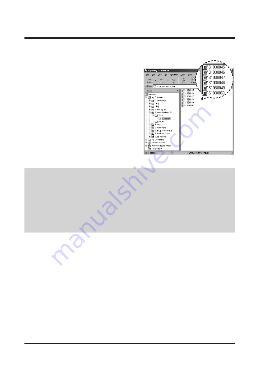
PDF documents of user manual are included in the Software CD-ROM supplied with this camera. Search the
PDF files with Window's explorer.
Before opening the PDF files, you must install the Adobe Reader included in the Software CD-ROM.
●
To install the Adobe Reader 6.0.1 correctly, Internet Explorer 5.01 or later had to be installed. Visit
"www.microsoft.com" and upgrade the Internet Explorer
4. Turn the camera power on.
The [Found New Hardware Wizard] will open and the
computer will recognise the camera.
※
If your OS is Windows XP, an image viewer program will
open.
If the download window of Digmax Master opens after
starting Digimax Master, the camera driver was set up
successfully.
Содержание S1000 - Digimax Digital Camera
Страница 1: ......
Страница 13: ...13 Ⅱ INSTALLATION FAQ ...
Страница 14: ...14 Ⅱ INSTALLATION FAQ ...
Страница 16: ...Ⅲ EXPLODED VIEW AND PART LIST 16 1 1 1 2 1 2 1 6 1 4 1 5 1 3 1 MAIN ASSEMBLY ...
Страница 19: ...22 Ⅲ EXPLODED VIEW AND PART LIST 4 3 4 1 4 4 4 4 4 9 4 5 4 6 4 7 4 8 4 7 4 2 4 2 4 BARRIER ASSEMBLY ...
Страница 22: ...28 Ⅲ EXPLODED VIEW AND PART LIST 7 BACK COVER ASSEMBLY 7 8 7 1 7 6 7 2 7 4 7 3 7 7 7 5 ...
Страница 65: ...68 Ⅴ PATTERN DIAGRAM 1 PARTS ARRANGEMENT FOR EACH PCB ASS Y 1 MAIN_TOP ...
Страница 66: ...69 Ⅴ PATTERN DIAGRAM 2 MAIN_BOTTOM ...
Страница 67: ...70 Ⅴ PATTERN DIAGRAM 3 MODE ...
Страница 68: ...71 Ⅴ PATTERN DIAGRAM 4 CCD ...
Страница 69: ...72 Ⅴ PATTERN DIAGRAM 5 FLASH ...
Страница 70: ...73 Ⅵ CIRCUIT DIAGRAM Ⅵ CIRCUIT DIAGRAM 1 MAIN ...
Страница 71: ...74 Ⅵ CIRCUIT DIAGRAM 2 MAIN_BLOCK ...
Страница 72: ...75 Ⅵ CIRCUIT DIAGRAM 3 MAIN_FEP ...
Страница 73: ...76 Ⅵ CIRCUIT DIAGRAM 4 MAIN_DDR MEMORY ...
Страница 74: ...77 Ⅵ CIRCUIT DIAGRAM N E P O R 0 9 6 1 R 5 MAIN_I O LCD ...
Страница 75: ...78 Ⅵ CIRCUIT DIAGRAM 6 MAIN_KEY ...
Страница 76: ...79 Ⅵ CIRCUIT DIAGRAM 7 MAIN_LENS MOTOR ...
Страница 77: ...80 Ⅵ CIRCUIT DIAGRAM 8 MAIN_POWER ...
Страница 78: ...81 Ⅵ CIRCUIT DIAGRAM 9 MAIN_STROBO ...
Страница 79: ...82 Ⅵ CIRCUIT DIAGRAM 10 CCD ...
Страница 80: ...83 Ⅵ CIRCUIT DIAGRAM 11 MODE ...
Страница 81: ...84 Ⅵ CIRCUIT DIAGRAM 12 STROBO ...
Страница 83: ...86 Ⅷ SERVICE INFORMATION Disassembly Camera 1 Remove 2 screws 2 Remove 2 screws 3 Remove 3 screws ...
Страница 86: ...89 Ⅷ SERVICE INFORMATION 10 Disconnect the PCB from the connector 11 Disassemble the FRONT COVER ...
Страница 88: ...91 Ⅷ SERVICE INFORMATION 15 Disassemble the MAIN PCB 16 Remove 3 screws 17 Disassemble the Barrel ASSY ...
Страница 89: ...92 Ⅶ SERVICE INFORMATION 18 Remove 2 screws 19 Disassemble the STROBE PCB ...
Страница 90: ...93 Ⅷ SERVICE INFORMATION Assemble Camera 1 Attach the STROBE PCB 2 Assemble 2 screws 3 Attach the Barrel ASSY ...
Страница 91: ...94 Ⅷ SERVICE INFORMATION 4 Assemble 3 screws 5 Attach the MAIN PCB 6 Connect the CCD PCB to the connector ...
Страница 98: ...101 Ⅶ SERVICE INFORMATION 9 Disassemble the Shutter Ass y After disassembling the Shutter Ass y ...
Страница 104: ...107 Ⅶ SERVICE INFORMATION 12 Assemble 3 screws and solder the Shutter F PCB h X 3 ...