


52
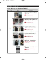
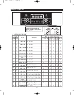
TROUBLE SHOOTING
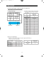
NO
Item
Description
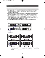
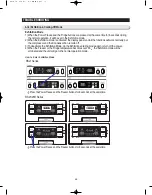
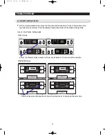
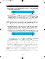
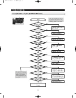
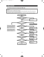
How to do Self-Diagnosis
FREEZER
SENSOR
FRIDGE
SENSOR
FREEZER
DEFROST
SENSOR
FRIDGE
DEFROST
SENSOR
AMBIENT
SENSOR
CoolSelect
ZONE
SENSOR
ICE
MAKER
SENSOR
FREEZER
FAN
ERROR
FRIDGE
FAN
ERROR
FREEZER
DEFROST
ERROR
FRIDGE
DEFROST
ERROR
ICE MAKER
ERROR
DAMPER
HEATER
ERROR
COMM
ERROR
CONDENSOR
FAN
ERROR
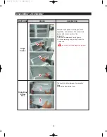
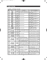
Connector Slipped-Out or Open-Cont act,
Wire Cut or Short-Circuited, Abnormal Sensing
Temp (+50°C and over or -50 °C and lower)
The voltage should be within the range
of 4.5V~1.0V between MAIN PCB
CN40 #5 and #8.
The voltage should be within the range
of 4.5V~1.0V between MAIN PCB
CN40 #9 and #8.
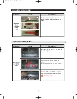
The voltage should be within the range
of 4.5V~1.0V between MAIN PCB
CN40 #6 and #8.
The voltage should be within the range
of 4.5V~1.0V between MAIN PCB
CN40 #11 and #8.
The voltage should be within the range
of 4.5V~1.0V between MAIN PCB
CN40 #2 and #1.
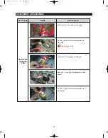
The voltage should be within the range
of 4.5V~1.0V between MAIN PCB
CN51 #13 and #14.
The voltage should be within the range
of 4.5V~1.0V between MAIN PCB
CN90 #3 and #8.
The voltage should be 7V~12V between
MAIN PCB CN75 GRAY and YELLOW.
The voltage should be 7V~12V between
MAIN PCB CN75 GRAY and ORANGE.
The voltage should be 7V~12V between
MAIN PCB CN75 GRAY and SKYBLUE.
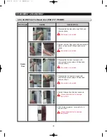
Disconnect MAIN PCB CN70, CN71 from PCB,
and read the resistance between Orange and
Brown wire terminals (Refer to the Wire Diagram
for the resistance value). 0 Ohm Heater Short
Ohm Wire Cut or Blown Thermistor.
Disconnect MAIN PCB CN70, CN71 from PCB,
and read the resistance between Orange and
White wire terminals (Refer to the Wire Diagram
for the resistance value). 0 Ohm
Heater Short
Ohm
Wire Cut or Blown Thermistor.
After replacing Ice-Maker, plug in the unit
and check its operation.
Disconnect MAIN PCB CN76 from PCB, and
read the resistance between Black and Brown
wire terminals (Refer to the Wire Diagram for the
resistance value). 0 Ohm
Heater Short
Ohm Wire Cut or Slipped-out Terminal
It needs a Oscilloscope to do the error check.
So, it is more realistic checking the error after
replacing Main or Panel PCB.
Same as the above
Same as the above
Same as the above
Same as the above
Same as the above
Same as the above
Same as the above
Same as the above
Bad Feed-Back Signaling Wire Conta
ct, Motor Wire Slipped-Out, Defective
Motor
Connector Slipped-Out or Open-
Contact, Wire Cut or Short-Circuited,
Defective Thermistor, or When it keeps
heating during Fridge Defrost even
after it does defrosting for 80 minutes.
Connector Slipped-Out or Open-
Contact, Wire Cut or Short-Circuited,
Defective Thermistor, or When it keeps
heating during Fridge Defrost even
after it does defrosting for 80 minutes.
I/M Ice Ejection Horizontal Positioning Error ** Only
for Dispenser models
Damper Heater is sensed as open
error due to Connector Slipped-Out or
Open-Contact, Wire Cut.
No communication between MICOM
MAI N and PANAL => The PC E error
code will light up with alarming sounds.
Digital no.
IHUMIDITY
SENSOR
Same as the above
The voltage should be within
the range of 4.5V~1.0V between
MAIN PCB CN40 #10 and #8.
Содержание RSJ1K Series
Страница 2: ......
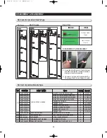
Страница 18: ...18 511 9 385 9 30 35 83 55 6 1663 5 1779 1702 908 D E F PRODUCT SPECIFICATIONS 2 4 Dimensions mm PRODUCT SIZE...
Страница 19: ...PRODUCT SPECIFICATIONS 2 5 Optional Material Specification 19 Photograph Part Name Part Code Quantity Remark...
Страница 68: ...TROUBLE SHOOTING SPM FREEWHEELING DIODE Voltage 68...
Страница 82: ...82 6 WIRING DIAGRAM 6 1 RS21 23H Series CHINA Z Option Inverter COMP...
Страница 83: ...83 WIRING DIAGRAM 6 2 RS21 23H Series CHINA V S Option Inverter COMP...
Страница 84: ...84 WIRING DIAGRAM 6 3 RS21 23H Series Z Y Option Inverter COMP...
Страница 85: ...85 WIRING DIAGRAM 6 4 RS21 23H Series P U Option Inverter COMP...
Страница 86: ...86 WIRING DIAGRAM 6 5 RS21 23H Series V S Option Inverter COMP...
Страница 87: ...87 WIRING DIAGRAM 6 6 RS21 23H Series K J Option AC COMP...
Страница 88: ...88 WIRING DIAGRAM 6 7 RS21 23H Series F D Option AC COMP...
Страница 89: ...89 WIRING DIAGRAM 6 8 RS21 23H Series B N Option AC COMP...
Страница 90: ...90 WIRING DIAGRAM 6 9 RSJ1 Series Z Option Inverter COMP...
Страница 91: ...91 WIRING DIAGRAM 6 10 RSJ1 Series P Option Inverter COMP...
Страница 92: ...92 WIRING DIAGRAM 6 11 RSJ1 Series K J Option AC COMP...
Страница 93: ...93 WIRING DIAGRAM 6 12 RSJ1 Series F D Option AC COMP...
Страница 94: ...94 94 7 SCHEMATIC DIAGRAM 7 1 Main PCB Schematic Diagram RSJ1 Series...
Страница 95: ...95 95 SCHEMATIC DIAGRAM 7 2 Main PCB Schematic Diagram RS21 23H Series...
Страница 96: ...96 SCHEMATIC DIAGRAM 7 3 Inverter PCB Schematic Diagram RSJ1 RS21 23H Series...
Страница 97: ...97 SCHEMATIC DIAGRAM 7 3 1 BLOCK DIAGRAM RS21 23H Series All...
Страница 98: ...98 SCHEMATIC DIAGRAM 7 3 2 BLOCK DIAGRAM RS21 23H Series Inverter COMP...
Страница 99: ...99 SCHEMATIC DIAGRAM 7 3 3 BLOCK DIAGRAM RS21 23H Series AC COMP...
Страница 100: ...8 REFERENCE INFORMATION Label Location 8 1 RSJ1 Series Nomenclature 100...
Страница 101: ...101 REFERENCE INFORMATION Label Location 8 2 RS21 23H Series Nomenclature...
Страница 106: ...106 REFERENCE INFORMATION 8 6 Air Circulation...


