81
5-11. Key Scan and Display Circuit
5. Circuit Descriptions
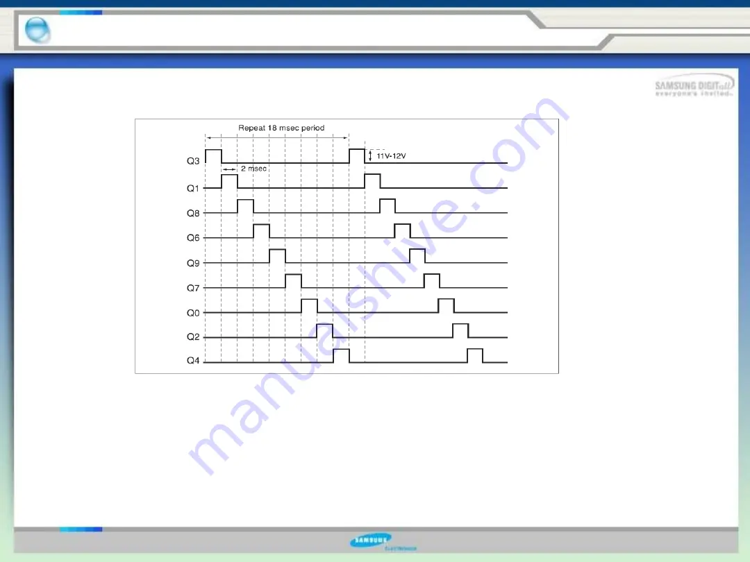
The step signals of DC 11
∼
12V will be generated periodically. If a sink signal
outputs from IC4, DC 11-12V will be applied to the LED input terminal and sink
the LED output terminal to 0V. Therefore, LED will be ON for 2 miliseconds.
2) Key Scan
The 6 step signals, Q6
∼
Q4 are applied to scan the 6 keys (buttons). When SW6
is pressed, the step signal from Q6
will be reduced to 5V and entered to the MICOM, then MICOM will match a
corresponding function for SW6 key.
Содержание RS277ACPN
Страница 14: ...15 1 7 Dimensions of Refrigerator inches 1 Product Information...
Страница 17: ...18 1 10 Cooling Air Circulation 1 Product Information Freezer Refrigerator...
Страница 47: ...48 4 Troubleshooting and major adjustment 4 1 Troubleshooting 4 1 1 If power is not ON Double Click...
Страница 51: ...52 4 Troubleshooting and major adjustment 4 1 Troubleshooting 4 1 5 If alarm sound Double Click...
Страница 53: ...54 4 1 Troubleshooting 4 1 7 If fan doesn t work 4 Troubleshooting and major adjustment Double Click...
Страница 70: ...71 5 1 Block diagram 5 Circuit Descriptions Double Click...
Страница 71: ...72 5 2 SCHEMATIC DIAGRAM 5 Circuit Descriptions Double Click...
Страница 72: ...73 5 3 WIRING DIAGRAM 5 Circuit Descriptions Double Click...
Страница 74: ...75 5 5 CONNECTOR ARRANGEMENT Main Board 5 Circuit Descriptions Double Click...
Страница 87: ...88 5 17 Load Drive Circuit 5 Circuit Descriptions Double Click...
Страница 92: ...93 6 Reference Information 6 2 Model name nomenclature...
Страница 93: ...94 The End Thank you...


