
97
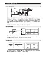
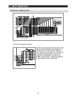
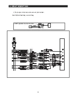
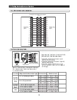
Check the condition in power on. Door
S/W have 2 contact points. One contact
point perceives the door open/close by
DC 5V on the PCB. Another contact point
turns on/off the Lamp.
(Lamp on the REF)
1. If the Lamp turns on correctly when the door is open, it is normal. Press the door s/w and check if the lamp turns
off. If it doesn’t work properly, check the door s/w on the refrigerator.
(Door open on the REF and the sensor part of the Main PCB)
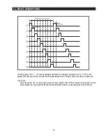
1. Check the voltage between no. 5 “+” terminal and no.6 “-” terminal of CN30.
2. If 5V is checked when the door is open, it is normal.
3. If 0V is checked when the door is closed, it is normal. If it is not, check the door s/w and electric wire connection.
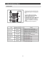
(Lamp on the FRE)
1. If the Lamp turns on correctly when the door is open, it is normal. Press the door s/w and check if the lamp turns
off. If it doesn’t work properly, check the door s/w on the FRE.
(Door open on the FRE and the sensor part of the Main PCB)
1. Check the voltage between no. 1 “+” terminal and no.2 “-” terminal of CN30.
2. If 5V is checked when the door is open, it is normal.
3. If 0V is checked when the door is closed, it is normal. If it is not, check the door s/w and electric wire connection.
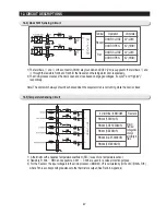
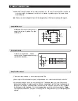
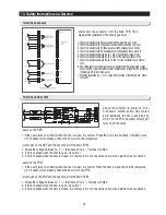
Disconnect the connector from the Main PCB, Then
measure the resistance of the following sensors.
1. Check the resistance the Freezer sensor cn30 between the no. 2 and 3.
2. Check the resistance the Fridge Room sensor cn30 between the no. 6 and 7.
3. Check the resistance the F Defrosting sensor cn30 between the no. 2 and 4.
4. Check the resistance the R Defrosting sensor cn30 between the no. 6 and 8.
5. Check the resistance between the no. 1 and 4 the ambient Air sensor cn31.
6. Check the resistance between the no. 3 and 4 of the Ice-Maker sensor cn90.
7. Check the resistance between the no. 13 and 14 of the CoolSelect Zone
TM
sensor
cn51.
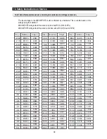
8. Decide the sensor by comparing the above resistances to the temperature of each
sensor with the conversion table of sensor resistance and voltage from the reference
temperature of Ref. 6 on this manual.
※
When the resistance is
∞Ω
or 0
Ω,
check the connection of electric wire and sensor
connector.
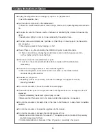
13. Safety Instructions on Service
13-4) Check sensors
13-5) Check Door S/W
Содержание RS265BBWP
Страница 18: ...18 Refrigerator 2 PRODUCT SPECIFICATIONS 2 9 Cooling Air Circulation Freezer...
Страница 68: ...7 EXPLODED VIEW PARTS LIST 7 3 Cabinet 7 1 69...
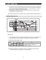
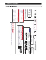
Страница 78: ...79 8 BLOCK DIAGRAM...
Страница 79: ...80 9 WIRING DIAGRAM 9 1 RS265BB RS267BB RS267LB RS269LB...
Страница 80: ...81 9 WIRING DIAGRAM 9 2 RS263BB RS265LB...
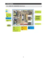
Страница 82: ...83 10 PCB DIAGRAM 10 2 CONNECTOR ARRANGEMENT Main Board...
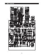
Страница 83: ...84 11 CIRCUIT DIAGRAM...


