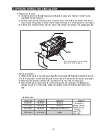
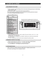
Samsung RS265BBWP Скачать руководство пользователя страница 38

Part name

Door Light

Switch

How To Do

The refrigerator has  a door light switch located
in the upper right corner for the refrigerator.

1. Use a small flat-blade screwdriver to unlock the

locking tab and pull the switch out until the wire
connector is visible.

38

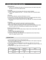
5. DISASSEMBLY AND REASSEMBLY

5-4) DOOR GASKET

Part name

Door Gasket

How To Do

Descriptive Picture

The door gasket is a molded gasket set into a
channel located in the door liner.

1.Open the door
2.Grasp the gasket and pull in an outward motion until the

molded gasket separates from the door liner.
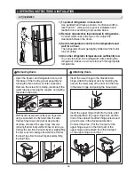
5-5) DOOR HANDLE

5-6) DOOR LIGHT SWITCH

Part name

Door Handle

How To Do

Descriptive Picture

The door handles allow access into the
refrigerator and freezer. They are front mounted
with screws.
Lift the handle upward motion with on.

Descriptive Picture

Part name

Tempered

Glass Shelf

How To Do

This shelves allow the storage of larger items
and pull out for easy access.

1. Pull the shelf out as far as it goes.
2. Lift it up and remove it.

5-7) TEMPERED GLASS SHELF

Descriptive Picture

Be careful not to scratch

Caution

Be careful of injury

Caution

Содержание RS265BBWP

Страница 1: ...IGITAL DISPLAY LED TOWER LIGHTING CONTOUR DOOR HIDDEN HINGE CLEAN LOOK DRAWER TWIN COOLING HUMAN TOUCH HANDLE SIDE BY SIDE BASIC RS265BBWP RS267LBBP MODEL NAME RS263BBWP RS265LBBP RS263BBBB RS265LBWP...

Страница 2: ...may result in personal injury and property damage The manufacturer or dealer cannot be responsible for the interpretation of this information SAMSUNG ELECTRONICS AMERICA INC Technical Service Guide Co...

Страница 3: ...TALLATION 20 4 ALIGNMENT AND ADJUSTMENTS 28 5 DISASSEMBLY AND REASSEMBLY 36 6 TROUBLESHOOTING 49 7 EXPLODED VIEW PARTS LIST 62 8 BLOCK DIAGRAM 79 9 WIRING DIAGRAM 80 10 PCB DIAGRAM 82 11 CIRCUIT DIAGR...

Страница 4: ...scriminately as before the repair Check the use circumstance of refrigerator If the refrigerator is installed at the place that is damp or wet or status of installation is unstable change the installa...

Страница 5: ...Caution Caution Unplug Use the rated components on the replacement Check the correct model rated voltage rated current operating temperature and so on On repair make sure that the wires such as harnes...

Страница 6: ...pening or closing the door may cause things to fall down with may inflict a wound Prohibition Prohibition Prohibition Prohibition Warning Caution Do not allow users to disassemble repair or alter It m...

Страница 7: ...tions 9 2 3 Interior Views 10 2 4 Model Specification Comparison Chart 11 2 5 Model Specification Comparison Chart 12 2 6 Dimensions of Refrigerator Inches 15 2 7 Optional Material Specification 16 2...

Страница 8: ...hrough multiple vents on every shelf level This provides even distribution of cooling inside cabinets to keep your food fresh longer Xtra SpaceTM Vertical room next to the ice maker in the freezer pro...

Страница 9: ...n PCB ASS Y Dispenser DA41 00396A Thermistor Freezer DA32 10109W Thermistor Freezer Evaporator DA32 00006A Thermistor Refrigerator DA32 10105U Thermistor Refrigerator Evaporator DA32 00006B Thermistor...

Страница 10: ...Tilt Pockets RS263B RS265L Model Egg Container Foldable Shelf RS265B RS267B RS267L RS269L Light upper Water Filter Spill proof glass Shelf Dairy Compartment Wine Shelf Gallon Door Bin Lights lower Ga...

Страница 11: ...4 6 1 1 24 0 23 7 24 7 20 4 1 3 0 3 3 4 1 1 1 3 0 9 1 7 1 0 1 5 1 2 2 1 3 3 53 2 55 5 48 8 55 3 44 4 43 3 45 0 46 7 41 3 41 1 40 0 45 0 Cooling Tech Door Shape Special Room Mono Cooling Mono Cooling...

Страница 12: ...quency Motor Rated Consumption Power ElectricHeaterRatedConsumptionPower Kind of Refrigerator Refrigerant Refrigerant Input Amount Product Weight Item Specification N Ne et t C Ca ap pa ac ciit ty y T...

Страница 13: ...0A Off 140 On 104 AC 250V 10A 170 6 0 10 Components for Freezer Room Temperature Sensor Components Freezer Model Temperature Selection 14 4 8 THERMISTOR F SENSOR 502AT Model Temperature Selection 34 3...

Страница 14: ...type Running Starting Model Operation Model Temp ON Temp OFF Starting Relay Over load Relay MOTOR BLDC FRE MOTOR BLDC REF MOTOR BLDC Circuit Lamp FRE Door Switch Power cord Earth Screw Bimetal thermo...

Страница 15: ...15 2 PRODUCT SPECIFICATIONS 35 9 46 8 16 3 21 2 51 7 20 3 30 5 36 5 34 3 15 3 1 2 4 3 70 2 6 Dimensions of Refrigerator Inches...

Страница 16: ...PRODUCT SPECIFICATIONS 2 7 Optional Material Specification Photographe Part Name FILTER WATER ASSY DA29 00003B ASSY PACKING SUB DA99 00240A LAMP INCANDENT 4713 001206 LAMP INCANDENT 4713 001197 Part...

Страница 17: ...ube Refrigerator Evaporator Freezer Evaporator Suction Pipe Compressor Refrigerator Evaporator Capillary Tube ACCUMULATOR Freezer Evaporator SUCTION PIPE Dryer Muffler SUB CONDENSER Hot Pipe Hot Pipe...

Страница 18: ...18 Refrigerator 2 PRODUCT SPECIFICATIONS 2 9 Cooling Air Circulation Freezer...

Страница 19: ...and Power Cool Functions 21 3 4 Child Lock Function 21 3 5 Ice Water Dispenser Function 22 3 6 C Fan Motor Delay Function of the Machine Compartment 22 3 7 CoolSelect ZoneTM Function RS267LA RS269LA...

Страница 20: ...ket is filled up with ice cubes When the ice bucket is filled up with ice cubes the freezer will run with original set temperature Also whenever the ice bucket is released from being filled with ice c...

Страница 21: ...e will be restored 2 Power Cool function 2 1 Power Cool operation and the indicator work exactly same as the Power Freeze function 2 2 When Power Cool is selected COMP and Refrigerator Fan operate con...

Страница 22: ...ter Dispenser function 2 1 To dispense water depress the water dispenser lever located in the dispenser recess 2 2 When the lever is depressed the water solenoid valve located in the machine compartme...

Страница 23: ...r will be maintained with 30 3 5 While the compressor is on this drawer retains a certain temperature and while the compressor is off the defrost heater is activated and Refrigerator Fan is on with a...

Страница 24: ...make ice any more because of a ice full signal 2 3 It takes 6 hours to harvest a first ice and throw away 2 3 times of these ice to make sure the supplied water clean 1 Initial Operation function 1 1...

Страница 25: ...water 5 3 When Cubed or Crushed option is selected again the control board will check an accumulated time period After making it 60 minutes and when the ice tray temperature is acceptable ice ejectio...

Страница 26: ...d pulling the hose down Insert the upper hinge shaft into the hole After leveling between the upper hinge hole and the hole of the cabinet Reattach hinge screws and ground screw in the clockwise direc...

Страница 27: ...rost Refrigerator Freezer Defrost Cancellation 28 4 2 Sound function 29 4 3 Cooling Off Function 29 4 4 Self Diagnostics Function 29 4 5 Load Operation Check Function 31 4 6 Restoration Function for P...

Страница 28: ...e If this pull down mode begins right after the compressor was off the compressor may not start to run due to an overload condition 1 3 At this mode the compressor and freezer fan will operate continu...

Страница 29: ...or operation are working properly 2 2 There is no defrost cycle in this mode 2 3 OF is displayed on F R Display 2 4 Cooling Off mode is not cleared even if power is reset 1 Self Diagnostics in the ini...

Страница 30: ...freezer room if frost removal mode is finished due to limited time of 70 minutes Error is displayed CONDENSER FAN ERROR COMP FAN The voltage should be 7V 12V between MAIN PCB CN72 4 S BLUE and 7 GRAY...

Страница 31: ...Power Cool buttons simultaneously for 12 seconds to get into this mode In this mode only the display LEDs for temperature will be ON NO Contents REFRIGERATOR FAN High or AC motor operation REFRIGERATO...

Страница 32: ...5 4 8 Table of Set Point Shift Function 4 ALIGNMENT AND ADJUSTMENTS 1 Initially all products set the code 0 2 After 20 seconds from adjustment a new setting will be stored in EEPROM and return to the...

Страница 33: ...3 4 5 6 7 8 9 10 11 12 13 14 15 Temp shift Code Temp shift 2 Shift the refrigerator temperature sensor 0 1 0 2 0 3 0 4 0 5 0 6 0 7 0 1 0 2 0 3 0 4 0 5 0 6 0 7 0 8 0 4 ALIGNMENT AND ADJUSTMENTS Example...

Страница 34: ...st the time to supply water for the ice maker 4 Shift the Ice maker temperature sensor 2 Reference Value 0 Code Volume to supply water 85 cc 1 95 cc 0 Code CoolSelect ZoneTM temperature sensor 0 1 1 0...

Страница 35: ...twork 40 5 13 Evaporator Fan Motor 41 5 14 Evaporator In Refrigerator 41 5 15 Door Bin In Freezer 41 5 16 Freezer Door Light Switch 42 5 17 Plastic Wire Drawer In Freezer 42 5 18 Freezer Shelf 42 5 19...

Страница 36: ...Take off the front leg cover by turning the three screw counter clockwise Removing the Water supply line 1 Remove the screw from clamp 2 Saparating the Water Supply Line from the Refrigertor by press...

Страница 37: ...at blade screwdriver on the slot as shown and unlock the tabs Disconnect the wire connector in the direction of the arrow Part name Door Ref Descriptive Picture How To Do Removing the Upper hinge 1 Wi...

Страница 38: ...door 2 Grasp the gasket and pull in an outward motion until the molded gasket separates from the door liner 5 5 DOOR HANDLE 5 6 DOOR LIGHT SWITCH Part name Door Handle How To Do Descriptive Picture T...

Страница 39: ...ins allow storage of perishable items 1 Push the bin up and slide it out How To Do The water filter is located in the upper right hand corner of the refrigerator The water filter filters water for the...

Страница 40: ...amp and thermistor 40 5 DISASSEMBLY AND REASSEMBLY Part name Evaporator Cover Descriptive Picture How To Do Remove the water tank from the evaporator cover by unscrewing the screws Remove the screws a...

Страница 41: ...ing soldering 6 Place a new evaporator and braze the suction and capillary tube to evaporator using silver solder 7 Install a replacement dryer 8 Evacuate and recharge the system using reasonable proc...

Страница 42: ...iptive Picture Descriptive Picture The shelves slide out for easy access for frozen items 1 Slide the shelf out until it reaches its stop 2 Tilt down and slide it out of the compartment 5 18 FREEZER S...

Страница 43: ...er This assembly stores ice made by the icemaker and dispenses ice 1 Lift the ice bucket up andslideouttheice dispenserassembly 5 19 ICE DISPENSER ICE MAKER Part name Ice Dispenser Ice Maker Descripti...

Страница 44: ...Light Descriptive Picture How To Do The freezer light is located in the bottom of the auger motor case The light is covered by an opaque cover 1 Remove the screw and the light cover 5 22 FREEZER LIGHT...

Страница 45: ...AN MOTOR Part name Evaporator In Freezer Descriptive Picture How To Do Evaporator is located in the bottom of freezer to produce cold air driven across the evaporator coils 1 Take off the ductwork in...

Страница 46: ...r Thermistor Part name Ice Maker Thermistor Descriptive Picture How To Do The Ice Maker thermistor is located in its bottom The temperature signal sends the micro processor 5 28 ICEMAKER THERMISTOR Pa...

Страница 47: ...the eight screws counter clockwise Disconnect the wire connector Remove the assy support circuit motor by unlocking the tabs and lifting it up Insert the flat tip screw driver into the fan and removi...

Страница 48: ...BLY Part name PROTECTOR O L PTC Descriptive Picture How To Do Insert the flat tip screwdriver into the fan and removing the cover relay along the arrow Remove the OLP or PTC along the arrow Remove the...

Страница 49: ...on 52 6 4 If there is a trouble with self diagnosis 53 6 5 If alarm sound 54 6 6 If the panel PCB is not working normally 56 6 7 If fan doesn t work 57 6 8 If CoolSelect ZoneTM isn t operated normally...

Страница 50: ...S W 233Y Is the voltage impressed DC 5 8V between C and S Is 12V impressed to both terminals of C102 Is the load such as relay normal Is normal the load such as relay Is there any PCB soldering short...

Страница 51: ...k with forced operation Is MICOM No 18 High 5V Open and repair the connection Troubleshoot the sensor and Exchange PCB IsthevoltageofIC03pinNo 14between0 1V Open and troubleshoot the connection Is COM...

Страница 52: ...heck temp fuse breaking of heater wire contact of wire and so on Is temp of the defrosting sensor below 5 Run forced operation for a specified period Repair the connection terminal Perform forced defr...

Страница 53: ...ents of Temperature Sensing Circuit section in the description of circuit operation A bad contact or connector missing Was the Main PCB connector CN31 inserted correctly Is the ambient temperature sen...

Страница 54: ...Troubleshoot the breaking of wire and bad door S W Main PCB and door S W are normal Yes NO No slightly YES NO Connector not inserted Troubleshoot poor contact NO Exchange the door S W NO YES Isthesta...

Страница 55: ...in the main PCB blackout or bent The main PCB and buzzer are normal YES YES NO NO YES NO NO Replace the main PCB failure of MICOM Aresignalscoming outofMICOMNo 21ina1 seccycle afterthe Forcedoperatio...

Страница 56: ...eCABIwireoffreezer checkthebreakingofwire shortbetweenwires 3 CheckforShort OpenofthePanelLightingCircuitsectioninthemainPCB NO NO YES YES NO Panel PCB itself has trouble YES YES Is lighting operated...

Страница 57: ...k if the fan motor has failure for itself 2 Check if the wire connections have a trouble of contact 3 Check the input of the fan motor rotation pulse in the operation motor fan See the details of Fan...

Страница 58: ...eofwireassemblybetween thepanelandmainPCB 1 CheckthewiresofCoolSelectZoneTM checkthedisconnectionofwire shortbetweenwires 2 CheckShort OpentheLightingCircuitsectionofCoolSelectZoneTM panelinthemainPCB...

Страница 59: ...S W Check the connections of F and R door S W check and troubleshoot the inside lamp socket YES NO NO YES Caution SeparatethedoorS Wandmeasureits resistancewithameasure Astheresult everyOpen Closeofth...

Страница 60: ...Main PCB IC3 and exchange it YES NO Does the contact shelf of RY77 relay turn 0 even in the power OFF FailureofMainPCB exchange ThecontactterminalofRY77 relayshortfailure YES NO FailureofMainPCBhas Ex...

Страница 61: ...62 7 EXPLODED VIEW PARTS LIST 7 1 Freezer 63 7 2 Refrigerator 66 7 3 Cabinet 69 7 4 Disassembly of Freeze Door 72 7 5 Disassembly of Refrigerator Door 75 7 6 Otherr 77...

Страница 62: ...7 8 18 8 15 8 12 8 5 8 6 8 7 7 8 4 1 3 2 1 3 1 3 5 4 2 2 2 5 5 2 5 1 2 6 2 7 2 9 2 8 4 2 4 1 1 2 1 1 2 10 2 4 2 3 6 6 2 6 6 6 9 6 4 6 3 9 1 13 16 2 15 1 13 2 15 16 16 15 16 1 17 17 17 1 17 1 17 2 18 1...

Страница 63: ...2AT ET PJT 50 50 5V 1 AD PJT 250V 10A 40 60 FIN AL 115V60HZ A TOP A TOP 06 PP COOL WHITE NORMAL BOX A TOP 06 PP COOL WHITE WIRE BOX SAPPHIRE PJT PP T2 0 290 769 5 WHITE A TOP PVC COVER EVAP FRE BLDC N...

Страница 64: ...A TOP 06 PP COOL WHITE NORMAL BOX LOWES05 GPPS AD HIPS COOL WHITE AD DISP AD URETHANE AD HIPS T2 5 SC 02740R AD ABS NTR AD PP T1 0 WHITE AD PP SC 93437R BJ73SLW180 AD 115V USP 05 750 COOL WHI A TOP LD...

Страница 65: ...23 1 23 24 25 15 2 15 5 15 4 15 7 15 10 22 1 22 2 15 9 15 6 15 2 1 15 2 2 15 1 1 15 8 20 1 15 3 16 17 16 2 16 1 17 2 17 1 28 28 1 28 2 18 28 3 19 1 3 4 3 6 3 8 3 7 3 9 3 2 3 5 6 2 2 3 2 10 2 6 2 8 2 2...

Страница 66: ...A TOP EVAP PP NTR ALL A TOP GALVANUME T0 4 A TOP AL 115V A TOP 06 PP DISPENSER CONVERTIBLE 30W SAPPHIRE PJT PP T2 5 409 647 Cool White NSBA001TA1 max 60mA DC12 V 60mA PRINTED HEATER 250V ATOP 06 3W 11...

Страница 67: ...WHITE SAPPHIRE HDPE 120V 340mA 40W FROST A TOP PP Cool white SC 02740R SAPPHIRE PP 44 128 599 NTR A TOP PP SC 02740R Cool white A TOP A TOP SBS LTC T10 W41 L41 BLK A TOP HIPS Cool white SC 02740R A TO...

Страница 68: ...7 EXPLODED VIEW PARTS LIST 7 3 Cabinet 7 1 69...

Страница 69: ...DA61 40126B CASTER REAR REF ALL PP PI44 NTR W22 2 9 DA60 90146A PIN CASTER MSWR10 OD6 0 L40 ZPC2 SR 289 4 2 10 DA61 30102A FOOT FRONT SR F5670 PP YEL T0 6 ZPC2 2 11 DA97 04049A ASSYCAP DRAIN EPEL ASS...

Страница 70: ...ONNECT NUT WATER LINE B TUBE FITTING VALVE WATER FITTING FIXER HOSE UL 1015 A 8 19cc 115V 60Hz RSCR QUEEN EPDM BEST BUY HIPS A TOP N ABS VH 0815 ATOP06 FR1 148 197115V 60Hz 12uF 250V BK 40X70 16mm A T...

Страница 71: ...EW PARTS LIST 7 4 Disassembly of Freeze Door 12 9 2 9 3 9 5 9 6 9 9 1 9 7 9 4 9 8 9 9 2 1 6 3 5 3 2 3 3 4 4 5 2 4 3 5 2 15 1 15 4 15 5 15 15 6 15 2 15 3 3 1 4 2 5 1 4 1 4 1 13 1 14 13 3 13 2 13 1 13 2...

Страница 72: ...115 60 2004 BBY W342 H1586 BLACK A TOP06 AL 6063 VERSAILLESSILVER A TOP06 AL A6063 VERSAILLESSILVER A TOP06 ABS MP 0160 MATUREBLACK A TOP06 ABS MP 0160 MATUREBLACK A TOP06 AL 6063 STAINLESSPLATINUM A...

Страница 73: ...ES05 50mm LOWES 05 HIPS T2 5 COOL WHITE LOWES 05 GPPS NTR LOWES05 50mm A TOP HIPS 50MM PREMIUM A TOP HIPS Cool white SC 02740R LOWES 05 GPPS NTR A TOP HIPP Cool white SC 02740R BBY 06 HIPS COOL WHITE...

Страница 74: ...75 7 EXPLODED VIEW PARTS LIST 7 5 Disassembly of Refrigerator Door 2 5 6 5 1 5 2 6 1 6 1 12 6 2 6 2 1 9 10 9 2 7 2 8 1 9 2 7 2 8 1 8 3 9 1 7 1 8 2 7 8 8 4 6 6...

Страница 75: ...50 HIPS COOL WHITE SC A TOP 50mm A TOP 50mm HIPS A TOP 50mm GPPS A TOP HIPP Cool white SC 02740R EXP BBY 06 HIPS COOL WHITE SC 02740R No BBY 06 HIPS COOL WHITE SC 02740R No USP GPPS Premium A TOP 06...

Страница 76: ...GE HANDLE REAR SEAL CUTT SPONGE SEAL CUTT SPONGE SCREW TAPPING SCREW TAPPING RELAY PTC DACT 100 W2 5 L101 6 NTR NYL DACT 200 W4 8 L190 NTR NYLON DA 275 T1 4 W6 2 L275 NTR NYLO BH 1 M4 L12 DAC WHT SWR...

Страница 77: ...SPONGE SEAL CUTT SPONGE SEAL CUTT SPONGE BRACKET PIPE WATER GUIDE ICE ROUTE PIPE WATER LINE SEAL CUTT SPONGE SWITCH MICRO SCREW TAPPING PIPE WATER WIRE HARNESS EARTH TUBE PVC PLATE EVAP FRE SUB SEAL A...

Страница 78: ...79 8 BLOCK DIAGRAM...

Страница 79: ...80 9 WIRING DIAGRAM 9 1 RS265BB RS267BB RS267LB RS269LB...

Страница 80: ...81 9 WIRING DIAGRAM 9 2 RS263BB RS265LB...

Страница 81: ...with MICOM and transfers them again 5 Plays role of operating the genuine room taste damper and the damper heater 6 Displays LED to the genuine room taste display driving part and processes key signa...

Страница 82: ...83 10 PCB DIAGRAM 10 2 CONNECTOR ARRANGEMENT Main Board...

Страница 83: ...84 11 CIRCUIT DIAGRAM...

Страница 84: ...6 12 3 Reset Circuit 86 12 4 Door S W Sensing Circuit 87 12 5 Temperature Sensing Circuit 87 12 6 Key Scan and Display Circuit 88 12 7 CoolSelect ZoneTM Panel Circuit 89 12 8 Fan Motor BLDC Drive Circ...

Страница 85: ...d voltage and transform into a steady 12V DC source power used for the digital display panel and relays The regulator KA7805 finally transforms into 5V DC source power for the control board and sensor...

Страница 86: ...ile the door is closed Terminal Operation Volt state Freezer DOOR CLOSE DOOR OPEN 0V LOW 5V HIGH Ref DOOR CLOSE DOOR OPEN 0V LOW 5V HIGH ofterminal in MICOM Remark PIN 49 F SENSOR PIN 50 F DEF SENSOR...

Страница 87: ...If the IC 9 decorder TC4028BP received signals from MICOM pins 3 6 an output signal per 2 miliseconds comes out from Q3 Q41 Q8 Q6 Q9 Q7 Q0 Q2 and Q4 pin in sequence This signal enters to a driver IC i...

Страница 88: ...applied to the LED input terminal and sink the LED output terminal to 0V Therefore LED will be ON for 2 miliseconds 2 Key Scan The 6 step signals Q6 Q4 are applied to scan the 6 keys buttons When SW6...

Страница 89: ...al display panel Panel LEDs are off while the doors are closed When a door is open micro processor senses its signal and LEDs will be on 1 3 The basic operational principle is the same as the key scan...

Страница 90: ...c12V 1 watt heater is mounted and activated continuously 1 Motor drive circuit 1 1 This refrigerator adopts a BLDC motor produces energy consumption Motors of the freezer refrigerator and the machine...

Страница 91: ...SSRs can control compressor refrigerator freezer defrost heater and several option functions 3 For compressor 18 pin of micro processor signals High 5V This signal inputs 5 pin of IC3 and 14 of outpu...

Страница 92: ...93 12 CIRCUIT DESCRIPTIONS 4 The principles of other loads are the same as 3 item described Note SSR Solid State Relay is a kind of Relay COMP equivalence circuit of drive section...

Страница 93: ...ssembled state when compared with the state before disassembly Check the surrounding conditions of the installed refrigerator When the refrigerator is located at humid or wet place or the installed st...

Страница 94: ...thterminalsofcontact DC 12V Working Condition DC 0V Stop Condition DC 12V load working condition DC 0V load stop condition DC 12V load working condition DC 0V load stop condition 2 contact terminal Re...

Страница 95: ...rouble Temperature fuse heater wires disconnection trouble Heater wires short trouble Heater wires and connector disconnection Coil wires short trouble Coil wires disconnection trouble Coil wires shor...

Страница 96: ...e Main PCB 1 Check the voltage between no 1 terminal and no 2 terminal of CN30 2 If 5V is checked when the door is open it is normal 3 If 0V is checked when the door is closed it is normal If it is no...

Страница 97: ...V Ground LEVEL Temp 12 2 14 0 15 8 17 6 19 4 21 2 23 0 24 8 26 6 28 4 30 2 32 0 33 8 35 6 37 4 39 2 41 0 42 8 44 6 46 4 48 2 50 0 51 8 53 6 55 4 57 2 59 0 60 8 62 6 64 4 66 2 Resistance 21 410 20 480...

Страница 98: ...T PX 41C CoolSelect ZoneTM MAIN PANEL Commonly used in ET PJT Main PCB ASS Y Main PCB ASS Y PANEL PCB ASS Y PANEL PCB ASS Y PANEL PCB ASS Y PANEL PCB ASS Y R DEFROST Sensor Ambient Temp Sensor F Temp...

Страница 99: ...100 14 REFERENCE INFORMATION 14 1 Model Name Nomenclature WW WHITE PCM Door Disassembly Replacement WP WW PCM CABI BB BLACK PCM Door Disasembly Replacement BP BLACK Lowe s PCM PCM CABI...

Страница 100: ...erator That makes refrigerator s temperature low quickly and save the power consumption Condensation can occur when you leave the door open for a long time Did you stop the ice making function Is ther...

Страница 101: ...ttom of the freezer clogged Cubes jammed in chute Supply line or shutoff valve is clogged Water filter clogged Dispenser is LOCKED Replace filter cartridge with new cartridge or with plug Check to see...

Страница 102: ...950 6193 6896 FAX 82 62 950 6829 Samsung Electronics Co Ltd Refrigerator Division 2005 06 Printed in Korea This Service Manual is a property of Samsung Electronics Co Ltd Any unauthorized use of Manua...

Отзывы: