Samsung Electronics
6-1
Schematic Diagram
This Document can not be used without Samsung’s authorization.
6. Schematic Diagram
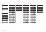
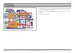
6-1 Overall Block Diagram
DP24 Mecha
Front
uCom
DVD/CD
Engine
64MB
DRAM
2M Flash
Video
4-Dac
Audio
Decoder
STA321
Function IC
EQ/3D
iPod
IR
AMP
3.0 CH
100W/CH
AUX1
USB
Host
SMPS
•
ZR36976
MPEG Chip
Tuner
AM5766
Motor Drive
Headphone
Headphone
OP AMP
LC87F5CC8A
Front Micom
Tuner Control
MECHA Control
PT6315
VFD Driver
Micom Update
Front End
Mic AMP
SMPS Control
Function
IC Control
R2S15904
MUX
I2S
DAB
Tx /Rx
iPod
SC
CVBS
Y Pb Pr
VFD
L/R Audio
#36, 37, 38, 39
MUTE
Sense
key Controller
T-Key
Video IC
LA73054
(iPod option)
#3, 6, 9, 12
DG36
option
L/R Audio
#42 AMP Mute
Line Out
OP AMP
HDMi
HDMi
CEC
iPod Control
DAB Control
Analog
Analog
Composit
Line L/R
MIX
OP
AMP
#89
Main System MICOM control PWM modulator IC (STA321), Turner, CD/DVD deck. They have a communication among
the with HOST ↔ SLAVE interface. And Main System MICOM gets the information from User’s remote control. So
whenever it gets the information, it displays it on the VFD.
The DVD/CD Deck, USB data is come from ZORAN IC(ZR36966) to STA321. STA321 mux this signal and convert to
PWM signal.
IR amp stage amplify this PWM signal.
Содержание MM-D530D
Страница 13: ...2 6 Samsung Electronics MEMO ...
Страница 19: ...3 6 Samsung Electronics MEMO ...
Страница 30: ...Samsung Electronics 5 1 PCB Diagram 5 PCB Diagram 5 1 Wiring Diagram ...
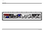
Страница 35: ...5 6 Samsung Electronics PCB Diagram 5 4 KEY PCB Top KEYCN1 TIC1 KEYIC2 ...
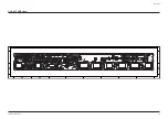
Страница 36: ...Samsung Electronics 5 7 PCB Diagram 5 5 KEY PCB Bottom ...
Страница 37: ...5 8 Samsung Electronics MEMO ...


