background image

Samsung Electronics

4-1

Troubleshooting

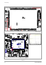
Check MAIN PCB IC21  

Pin 14, 40, 55, 89: 5V?

Yes

No

Check MAIN PCB  

IC1P104 Pin 1: 5.6V,

Pin 5: 0.7V, Pin: 1V?

Yes

No Power

No

1. Check pattern or replace 

IC1P104.

2. Check SMPS part (high 

voltage, danger).

1

Check MAIN PCB  

IC21 Pin 1: 5V (High)

Yes

Check MAIN PCB  

C525 (VFD+), C530 (VFD-),  

C531 (-VP)

Check MAIN PCB 

T1 Pin 12: HIGH

No

Yes

No

No

Replace MICOM IC

2

Check IC21 Pin 8  

(Micom Reset), X-TAL2,  

X-TAL3

Yes

Check or replace signal line, 

X-TAL

No

 Refer to wave pattern 

image of Fig. 4-1.

1. Check pattern or replace 

UF4007.

2. Check SMPS part (high 

voltage, danger).

Check MAIN PCB  

PT01 Pin 10, 11, 12

No

1. Check 1SQ22 (about ECO 

mode) work status

2. Check pattern or replace 

them

3. Check SMPS part (high 

voltage, danger).

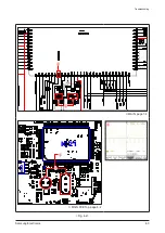
 Refer to wave pattern 

image of Fig. 4-2.

4. Troubleshooting

4-1  Checkpoints by Error Mode

4-1-1  No Power

Содержание MM-D530D

Страница 1: ...odel Code MM D530D RU PERSONAL MICRO COMPONENT SYSTEM Refer to the service manual in the GSPN see the rear cover for the more information CONTENTS 1 Precaution 2 Product Specification 3 Disassembly Reassembly 4 Troubleshooting 5 PCB Diagram 6 Schematic Diagram MM D530D ...

Страница 2: ...er applicable International and or domestic law GSPN Global Service Partner Network Area Web Site Europe MENA CIS Africa https gspn1 samsungcsportal com E Asia W Asia China Japan https gspn2 samsungcsportal com N America S America https gspn3 samsungcsportal com Samsung Electronics Co Ltd Apr 2011 Printed in Korea ...

Страница 3: ...mbly 3 1 Overall Disassembly Reassembly 3 1 4 Troubleshooting 4 1 Checkpoints by Error Mode 4 1 4 2 Measures to be taken when the Protection Circuit operates 4 6 4 3 MICOM MPEG Initialization Update 4 7 4 4 Buyer Region Code Setting Method 4 8 5 PCB Diagram 5 1 Wiring Diagram 5 1 5 2 MAIN PCB Top 5 2 5 3 MAIN PCB Bottom 5 5 5 4 KEY PCB Top 5 6 5 5 KEY PCB Bottom 5 7 6 Schematic Diagram 6 1 Overall...

Страница 4: ...ces and Underwriters Laboratories UL Publication UL1410 59 7 With the unit completely reassembled plug the AC cord directly into a 120V AC outlet With the unit s power switched from the ON to the OFF position measure the current between a known ground and all exposed metal parts Known Grounds Earth Known Metal parts screwheads metal cabinets etc 5 Insulation Resistance Cold Check 1 With the unit s...

Страница 5: ... AC power cord for damage Make sure that no wires or components touch thermally hot parts 8 Product Safety Notice Some electrical and mechanical parts have special safety related characteristics which might not be obvious from visual inspection These safety features and the protection they give might be lost if the replacement component differs from the original even if the replacement is rated fo...

Страница 6: ...d part has not been damaged 5 Check the insulation between the blades of the AC plug and accessible conductive parts examples metal panels input terminals and earphone jacks 6 Insulation Checking Procedure Disconnect the power cord from the AC source Connect an insulation resistance meter 500V to the blades of the AC plug The insulation resistance between each blade of the AC plug and accessible c...

Страница 7: ...mulation of electrostatic charge 3 Do not use freon propelled chemicals These can generate electrical charges that damage ESDs 4 Use only a grounded tip soldering iron when soldering or unsoldering ESDs 5 Use only an anti static solder removal device Many solder removal devices are not rated as anti static these can accumulate sufficient electrical charge to damage ESDs 6 Do not remove a replaceme...

Страница 8: ...ure 2 CH Powerful Sound Experience 120W Powerr USB Host w video playback Tuner iPod Option DAB Option Various Multimedia Playback MP3 WMA 2 1 2 MM D530D Product Feature 2 CH Powerful Sound Experience 160W Power DVD Disc USB Host w video playback Tuner iPod Option DAB Option Various Multimedia Playback DIVX MP3 WMA photo files ...

Страница 9: ...C PLAYER Capacity 1 discs Frequency range 20 Hz 20 KHz 1 dB Signal noise ratio 90 dB at 1 KHz with filter Distortion 0 05 at 1 KHz Channel separation 60 dB Disc sizes Diameter 120 or 80 mm Thickness 1 2 mm AMPLIFLER Front Speaker 8Ω 60W CH X2 RMS IEC total harmonic distortion 10 MM D430 MM D430D Channel separation 60 dB Signal noise ratio 70 dB GENERAL Power Consumption 40W Dimensions 230 D x 98 H...

Страница 10: ...apacity 1 discs Frequency range 20 Hz 20 KHz 1 dB Signal noise ratio 90 dB at 1 KHz with filter Distortion 0 05 at 1 KHz Channel separation 60 dB Disc sizes Diameter 120 or 80 mm Thickness 1 2 mm AMPLIFLER Front Speaker 6Ω 80W CH X2 RMS IEC total harmonic distortion 10 MM D530D Channel separation 60 dB Signal noise ratio 70 dB GENERAL Power Consumption 40W Dimensions 230 D x 98 H x 240 W mm Weight...

Страница 11: ...Name MM D430 MM D430D MM D530D MM DG35 Photo Output Power 2CH 120W 2CH 160W 2CH 160W Front Display VFD VFD VFD Key Switch Touch Touch Touch CD DVD DVD DVD DVD TAPE X X X USB HOST CD RIPPING EQ DSP DNSe DNSe DNSe Aux In MIC FM DAB UK SPK Impedance 6 4 6 application X non application ...

Страница 12: ...on 2 4 Accessories 2 4 1 Supplied Accessories Accessories Item Item code Remark Remote Control AH59 02146H Samsung Service Center iPod Dock AH96 00051A Battery 4301 000116 Audio Cable AH39 40001V FM Antenna AH42 00021A User s Manual AH68 02344P ...

Страница 13: ...2 6 Samsung Electronics MEMO ...

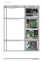
Страница 14: ...ence described in the manual Otherwise the product may be damaged Be sure to carefully read and understand the safety instructions before performing any work as the IC chips on the PCB are vulnerable to static electricity Assemble in the reverse order of disassembly No Description Description Photo 1 1 Unfasten 1 8EA screws on the CABINET SIDE back ...

Страница 15: ...3 2 Samsung Electronics Disassembly Reassembly No Description Description Photo 2 1 Unfasten 3 2EA 1EA screws on the CABINET TOP side and middle 3 1 Unfasten 7 screws 4 1 Unfasten 1 screw ...

Страница 16: ...Samsung Electronics 3 3 Disassembly Reassembly No Description Description Photo 4 5 1 Turn over the hook of CABINET BOTTOM and separate ASSY FRONT Unfasten 2 1EA 2 screws ...

Страница 17: ...3 4 Samsung Electronics Disassembly Reassembly No Description Description Photo 6 1 Turn off the Spring Door 7 1 Unfasten 4 screws on the MAIN PCB 8 1 Unfasten 3 screws on the DECK MECHA ...

Страница 18: ...Samsung Electronics 3 5 Disassembly Reassembly No Description Description Photo 8 9 1 Unfasten 2 screws on the MPEG PCB 10 1 BOTTOM ...

Страница 19: ...3 6 Samsung Electronics MEMO ...

Страница 20: ...P Check MAIN PCB T1 Pin 12 HIGH No Yes No No Replace MICOM IC 2 Check IC21 Pin 8 Micom Reset X TAL2 X TAL3 Yes Check or replace signal line X TAL No Refer to wave pattern image of Fig 4 1 1 Check pattern or replace UF4007 2 Check SMPS part high voltage danger Check MAIN PCB PT01 Pin 10 11 12 No 1 Check 1SQ22 about ECO mode work status 2 Check pattern or replace them 3 Check SMPS part high voltage ...

Страница 21: ...4 2 Samsung Electronics Troubleshooting MAIN page 7 4 IC21 IC22 IC814 IC IC13 IC15 MAIN PCB Top page 6 2 Fig 4 1 1 1 1 ...

Страница 22: ...Samsung Electronics 4 3 Troubleshooting MAIN page 7 4 IC21 IC22 IC814 IC IC13 IC1P104 IC15 MAIN PCB Top page 6 2 Fig 4 2 2 2 2 2 2 ...

Страница 23: ...Check MAIN PCB IC9 Pin 19 Low Mute High Normal Check AUX IC9 Power GND pattern and signal pattern Check MICOM IC21 Pin 44 Low Normal High Mute Yes No Yes No Yes No SPK No output Check signal input of AUX R L pattern from JACK521 Replace IC9 Check MAIN PCB L1S31 24V L1S30 24V Check power pattern Yes No Refer to wave pattern image of Fig 4 3 ...

Страница 24: ...Samsung Electronics 4 5 Troubleshooting MAIN page 7 4 PCW1 IC2 IC8 IC9 C16 IC17 IC3 MAIN PCB Top page 6 2 Fig 4 3 1 1 1 ...

Страница 25: ...otection If you think there are problems at the AMP part you can check the pcb without disassemble the set Caution Do not connect the power cord during bellow test Measurement Resistance using Tester Approximately CH MM D430D D530D L R CH 1 kΩ Table 4 1 If Measured Resistance is very different from above numbers There is a Problem AMP PART Problem ...

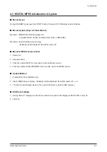
Страница 26: ...l be displayed Set will be power off Micom MPEG Version Check 1 Power On 2 CD open status 3 Push the number NEXT for 5 seconds check the Micom version 4 Push the number PREVIOUS INFO for 5 seconds check the MPEG version Update Method 1 Prepare Rom file at USB Memory 2 Insert USB Memory and play Updating will be displayed Set will be power off on 3 The disc is automatically ejected If you use USB m...

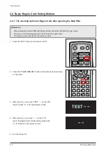
Страница 27: ...ot working properly if you don t insert the region code The region code is inserted by the remote control 1 Press the AUX button on the remote control 2 Press the TUNER MEMORY button on the remote control during 4 5 seconds 3 After step 2 you can see TEST on the VFD Insert number 3 3 to select Region Code 4 After step 3 you can see on the VFD Insert the Region Code corresponding model with 0 9 but...

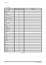
Страница 28: ...A 02 China semi_mic 03 Europe 04 Indonesia HONGKONG 05 JAPAN 06 KOR 07 Latin American 08 Mexico 09 Philippines 10 Russia full_mic 11 Russia semi_mic 12 South Africa 13 Taiwan 14 USA 15 Newzealand 16 England 17 Australia 18 Iran HACO 19 India 20 Israel 21 Middle Asia 22 Asia 23 Singapore 24 THAILAND 25 MOROCCO 26 Table 4 2 ...

Страница 29: ...DA 32 China semi_mic 33 Europe 34 Indonesia HONGKONG 35 JAPAN 36 KOR 37 Latin American 38 Mexico 39 Philippines 40 Russia full_mic 41 Russia semi_mic 42 South Africa 43 Taiwan 44 USA 45 Newzealand 46 England 47 Australia 48 Iran HACO 49 India 50 Israel 51 Middle Asia 52 Asia 53 Singapore 54 THAILAND 55 MOROCCO 56 Table 4 3 ...

Страница 30: ...Samsung Electronics 5 1 PCB Diagram 5 PCB Diagram 5 1 Wiring Diagram ...

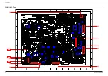
Страница 31: ... MAIN PCB Top 1 2 3 4 5 6 7 8 9 TP1 TP3 TP2 1SIC01 2SIC01 MIC1 MIC3 MIC5 MIC2 IPIC1 IC21 IC22 IC814 IC522 CON6 DCON10 CON5 PCW1 IPCON1 MCON2 MCON1 RFCON1 DCON1 IC2 IC8 IC7 IC13 IC9 IC1P104 IC15 IC16 IC17 IC3 DIC1 HIC31 KIC1 MIC4 HIC32 IPIC3 ...

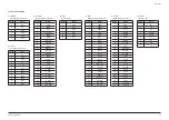
Страница 32: ...LED3 10 LED4 11 LED5 12 LED6 4 CON5 Micom Update Pin No Signal 1 GND 2 RST 3 DP0 4 DP1 5 DP2 6 N C 5 PCW1 MPEG Power Signal Connector Pin No Signal 1 USB5V 2 USB5V 3 USB5V 4 GND 5 GND 6 M5V 7 M5V 8 DGND 9 DGND 10 D3 3V 11 D3 3V 12 MCLK 13 TSD0 14 LRCLK 15 B_CLK 16 HDMI_5 6V 17 TV_SW 18 LINE_L 19 SGND 20 LINE_R 21 iPod_DET 22 AN_RCH 23 iPod_VSW 24 AN_LCH 6 MCON1 MPEG PCB Data Connector Pin No Signa...

Страница 33: ... 6 M5V 7 M5V 8 DGND 9 DGND 10 D3 3V 11 D3 3V 12 MCLK 13 TSD0 14 LRCLK 15 B_CLK 16 HDMI_5 6V 17 TV_SW 18 LINE_L 19 SGND 20 LINE_R 21 iPod_DET 22 AN_RCH 23 iPod_VSW 24 AN_LCH TP3 8 RFCON1 DECK Data Pin No Signal 1 CD VR 2 MPD 3 CD LD 4 LD GND 5 SW 6 F 7 T 8 T 9 F 10 B 11 C 12 D 13 A 14 E 15 F 16 Vcc 17 Vref 18 GND 19 DVD VR 20 PD 21 DVD LD 22 RFCON1 23 H Vcc ...

Страница 34: ...Samsung Electronics 5 5 PCB Diagram 5 3 MAIN PCB Bottom 1SIC01 2SIC01 CON6 DCON10 CON5 PCW1 MCON2 MCON1 RFCON1 DCON1 ...

Страница 35: ...5 6 Samsung Electronics PCB Diagram 5 4 KEY PCB Top KEYCN1 TIC1 KEYIC2 ...

Страница 36: ...Samsung Electronics 5 7 PCB Diagram 5 5 KEY PCB Bottom ...

Страница 37: ...5 8 Samsung Electronics MEMO ...

Страница 38: ...ontrol R2S15904 MUX I2S DAB Tx Rx iPod SC CVBS Y Pb Pr VFD L R Audio 36 37 38 39 MUTE Sense key Controller T Key Video IC LA73054 iPod option 3 6 9 12 DG36 option L R Audio 42 AMP Mute Line Out OP AMP HDMi HDMi CEC iPod Control DAB Control Analog Analog Composit Line L R MIX OP AMP 89 Main System MICOM control PWM modulator IC STA321 Turner CD DVD deck They have a communication among the with HOST...

Страница 39: ...6 2 Samsung Electronics Schematic Diagram This Document can not be used without Samsung s authorization 6 2 FRONT ...

Страница 40: ...1 10W 1 0 LED 2 LED 4 4 LED 5 LED 6 5 6 LED 0 LED 7 7 0 LED 1 1 1 10W 220OHM 1 10W 1 10W 1 10W DATA 0 7 220OHM 1 10W SSC TWH104 HS SSC TWH104 HS 1 10W 390OHM 1 10W 390OHM 1 10W 390OHM 16V 1 10W 25V 1 10W 390OHM GND 1 10W 1 10W 1 10W 470KOHM 470KOHM 220KOHM 220KOHM 75 1N4148WS 75 1N4148WS 75 1N4148WS 75 1N4148WS GND 2 2KOHM 0OHM SWQ2 KEYR13 KEYR14 KPD4 EJECT FUNCTION FF STOP KPD3 KPD2 KEYBD2 KEYDB1...

Страница 41: ...6 4 Samsung Electronics Schematic Diagram This Document can not be used without Samsung s authorization 6 4 MAIN TP3 TP1 TP2 TP2 POWER AUDIO TP1 TP2 TP3 ...

Страница 42: ...Samsung Electronics 6 5 Schematic Diagram This Document can not be used without Samsung s authorization 6 5 MPEG POWER AUDIO VIDEO ...

Страница 43: ...6 6 Samsung Electronics Schematic Diagram This Document can not be used without Samsung s authorization 6 6 SMPS POWER ...

Отзывы: