Service Manual
System Diagram
6-1
Samsung Electronics
Main
S/
W
INLET
MAIN
SMPS
SPGPv
3
HVPS
FUSER Unit
ThermoStat
Thermistor
PaperExit
Sensor
OPE
KEY LED1 LED
2
PickUp
Clutch
Regist
Clutch
Front Cover
Micro Switch
Rear Cover
Micro Switch
5V
24
V
FUSER ON
5V
24
V
24
VS
24
VS
24
V
DEVELOPER Unit
FAN
MAIN
FAN
LSU
OPC
MHV
DEV
Supply
THV
Varistor
T
D
S
DRUM
M
Main
Motor
MT
BLDC
NOR Flash
S2
9
G
L
3
2
0
M
(4
MB X
2
E
A
)
SDRAM
K4
S2
8
1
6
3
2
(1
6
M
B X
2
E
A
)
MCLK
12
MHz
VCLK
12
MHz
EEPROM
M
2
4
C
32
W X
2E
A
Содержание ML-2851ND
Страница 52: ...Service Manual Alignment Troubleshooting 4 3 Samsung Electronics ...
Страница 114: ...Service Manual ExplodedView and Parts list 5 4 Samsung Electronics 5 2 Top Cover 0 1 2 3 3 5 7 8 9 10 ...
Страница 116: ...Service Manual ExplodedView and Parts list 5 6 Samsung Electronics 5 3 Cover Ass y 0 1 2 3 3 1 3 2 4 ...
Страница 118: ...Service Manual ExplodedView and Parts list 5 8 Samsung Electronics 5 4 Front Cover 0 1 2 3 4 5 ...
Страница 120: ...Service Manual ExplodedView and Parts list 5 10 Samsung Electronics 5 5 Rear Cover 0 2 1 ...
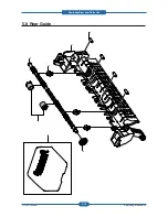
Страница 129: ...Service Manual ExplodedView and Parts list 5 19 Samsung Electronics 5 8 Rear Guide 0 1 2 3 4 5 6 ...


