background image

Samsung Electronics 

32 

18 

17 

14 

13 

10 

19 

16 

15 

12 

11 

ID:

2  3 

11 

13 

18 

19 

10 

14 

16 

17 

ID:

15 

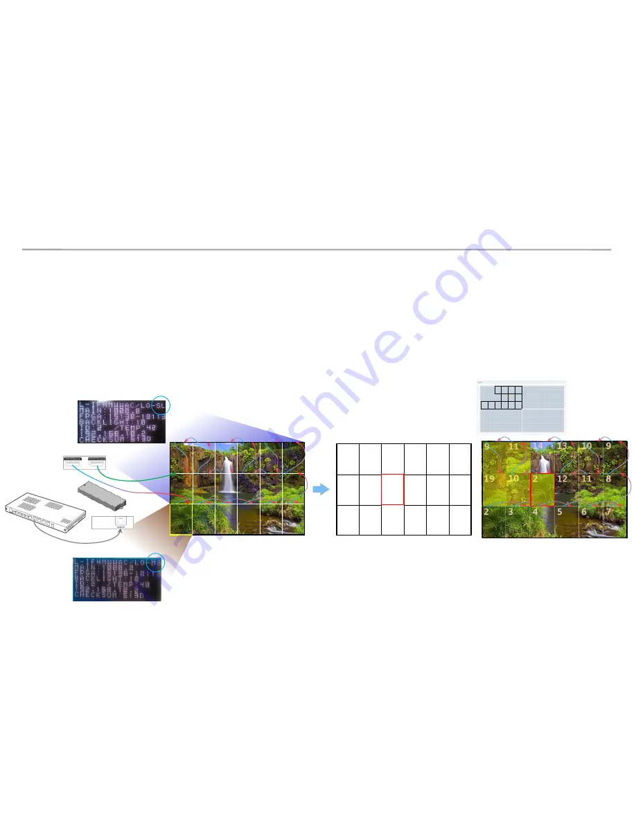
The factory reset of 1

st

 cabinet is done 

From ID 2 to ID13, the LSM connection will 

be OK. 

but 14

th

 cabinet will be connection fail. 

Over 14

th

 cabinet the picture 

might be not correct. Because of 

2

nd

 Master cabinet 

HDB-T(LVDS) 

OCM(Vx1) 

OCM(Vx1) 

Redundancy 


Master 


Master 


14  13  10  9 

12  11  8 

2  3  4  5  6  7 

Rule 1:  The 1

st

 Cabinet from I/G board must be ID #2 for the LSM Setup 

Rule 2:  The 1

st

 Cabinet from I/G board must be set as Master. The 2

nd

 Master cabinet is not allowed for the LSM connection. 

Situation: After changing Main board or Cabinet, If the original Master cabinet is move to slave cabinet area. 
             Although the 1

st

 cabinet is set as a Master after doing factory reset, LSM configuration will be still fail  

              because of violation of rule 2. LSM setup can be start, but can’t be complete because of the 2

nd

 Master cabinet. 

Problem Case 1 

7. Issue and Solution 

Solution: Do Factory Reset the 2

nd

 Master Cabinet 

Re- install 

Содержание LH015IFH SERIES

Страница 1: ...Samsung Electronics LED Display Installation Manual LH015IFH P1 5 LH020IFH P2 0 LH025IFH P2 5 SBB SNOWH3U Ver 1 0 ...

Страница 2: ...oduct Information and Precautions for Installation 2 Preparation for Cabinet Installation 3 Frame Installation 4 Cabinet Frame Installation 5 SBOX Connection 6 Settings and How to Use 7 Issue and Solution 8 Cable Connection 9 Seam Adjustment 1 ...

Страница 3: ...Frame Kit Composition Note CY LFH15FWA 6 3 18 Set FHD Installation for P1 5 Standard CY LFH20FWA 8 4 32 Set FHD Installation for P2 0 Standard CY LFH25FWA 10 5 50 Set FHD Installation for P2 5 Standard Fig 3 S Box Fig 4 I G Interface Gender SBB SNOWH3F U S Box I G Fig 1 6 3 Cabinet Product Information Fig2 Fig 2 2 ...

Страница 4: ...he outside Beware not to put the LED side headed downwards to the floor after the protection gets taken off for installation Beware not to put more than 12 layers Beware of LED Damage due to Static Electricity Beware not to touch LED screen with bare hands without putting gloves on Beware of LED Damage due to Metallic Substances Beware not to have metallic substances pulled in to the surface due t...

Страница 5: ...Product Information and Precautions for Installation Preparations for Installation 10 0mm Wrench LED MODULE JIG model name CY LJFNAS Electric Driver Driver Plier Service JIG BH81 00001A Holder Magnet Tool Antistatic Glove 4 ...

Страница 6: ...emoval SLIDING SCREW In Exclusive Frame Accessory 9 Page ⓓ Outermost Hole Remove the Box tape at the upper area and then open up the box Fig 1 Remove the Top Cushion and hold the handle inside PE Bag and pull out the set then remove PE bag Fig 2 Press the hook area and then bend backwards to separate the Cover Connector Fig 3 Assemble four 4 Sliding Screw for installation at the hole located at th...

Страница 7: ...e electricity If the information screen comes out press the Switch button to switch the screens on W Pattern and check the screens Unfasten the screws total of four 4 on the Cover Corner area to separate those screws Fig 6 Put the Cabinet on the Cushion Top so that the LED screen will head upwards Fig 7 Cushion Top Screw Switch Button Fig 5 Check the Screen Fig 6 Cover Corner Removal Fig 7 Cabinet...

Страница 8: ...en Internal white pattern Turn on Power Push Source button 5 seconds and release Wait for display push one more times color rotation White Blue Red Green Push button for 5 seconds again to exit factory OSD Switch Button Power In Power out 2 Preparation for Cabinet Installation Reference Process of Screen check 7 ...

Страница 9: ...t Cover PCB should be at the boundary of whole screen Blue area at the exterior of Fig 1 Attach PET Sheet as shown below Fig 3 The areas where there is no tape should guide the LED module Assemble the Cover PCB as shown below Fig 4 Fig 1 Sheet PET Cover PCB Fig 3 Fig 4 PET Sheet No Tape 0 0 5mm 8 Fig 1 Attach point of Sheet PET Fig 1 Attach point of Sheet PET ...

Страница 10: ... Units ⓐ ASSY BRACKET SIDE 2 2 2 ⓑ ASSY BRACKET CENTER 6 8 10 ⓒ ASSY BRACKET JIG 2 2 2 ⓓ ASSY SLIDING SCREW 76 132 204 ⓔ ASSY ANCHOR SCREW 32 50 72 ⓕ MANUAL INSTALL 1 1 1 Size of the Installation Screen mm 2880X1620 3840X2160 4800X2700 3 Frame Installation Frame Kit Composition d e f 9 M5 L65 Anchor screw ...

Страница 11: ...ent Then fasten up the remaining holes Refer to Page 11 for the Precautions for fixing the Screws Order of Fastening the Screws No 1 No 2 No 3 No 4 Fig 1 ⓐ Bracket Side is located at 7mm of the end line of the screen Fig 4 Fastened Hole Reserved hole No 1 Fig 1 Order of Work No 2 No 3 No 4 Fig 2 Reserved Holes a a b b b b b c Fig 3 Location of Components 10 Fig 4 Distance between Screen and Bracke...

Страница 12: ...Samsung Electronics 3 Frame Installation Precautions for Fastening the Screws 11 ...

Страница 13: ... Warning ⓐ ⓑand ⓒ sides should be attached and the three 3 sides of Wall Frame side Jig side should be parallel Fig 4 Install in the same way from left to right The farthermost right side the last side should be installed using ⓐBracket Side Fig1 Check the Hole Fig2 Fix the Jig Screw Fig4 Maintain the Parallel Frame Fig3 Fasten the Screw ⓐ ⓑ Wall Wrong Installation X Correct Installation O ⓒ a a b...

Страница 14: ...ach Type Fig 1 Location to Install Locate the I G at the point 35 40mm below which is the standard for carving at the right side of the frame and then fasten the screws Fig 2 35 40mm I G Fix I G Location Fig1 Location to Fix the I G and Order of Installing the Cabinet Fig2 Location to Fix I G 70 80mm 13 ...

Страница 15: ...of the Frame and assemble so that it slides towards downward diagonal direction Fig 2 From the layers above the second floor insert the Service Jig between each Cabinet remove the Service Jig slowly lower the Cabinet Fig 3 Beware not to have the Service Jig touch the LED Module Check whether the gap between each module widens whether the size of the pitch differs every time of installation Marked ...

Страница 16: ... for Protection Bracket Material Aluminum or steel thickness 1 0mm 2 0mm black coating Dimension Width 49mm Length 1610 8mm 2150 5mm 2690 2mm same with Frame Fig 2 Screw hole position interval 200mm first screw has distance 90mm to bottom line Fig 3 Screw M4 0 7mm length 6mm Protection Fig 1 Protection Protection Fig 3 Screw location 90mm Interval 200mm 49mm Fig 2 Protection dimension M4 screw hol...

Страница 17: ...pe cable Input the video signal to the S BOX Input terminal HDMI DP Check the signal input from SOURCE STATUS RED HDMI1 GREEN HDMI2 Blue DISPLAY PORT Connect from the HDBT OUT port of S BOX to HDBT IN port of Interface Gender using LAN cable Connect from DATA OUT port of Interface Gender to DATA IN port of the first cabinet using OCM Cable 16 ...

Страница 18: ... For HDBT signal stability use the cable above CAT6 SFTP level Length 15m 100m Do not use comb or pinstripe cable If Redundant Spec should be used Connect from DATA IN port of Interface Gender to DATA OUT port of the last cabinet by using OCM Cable 17 ...

Страница 19: ...ng Electronics 6 1 Control Program for PCs 6 Settings and How to Use LSM LED Signage Manager LSM Download Path GSBN SLM Display solution download LED SIGNAGE MANAGER or LSM GSBN http v3 samsunggsbn com ep 18 ...

Страница 20: ...2 S box is connected to Interface Gender using HDB T Lan Cable 3 Interface Gender is connected to the first LED Cabinet using OCM cable 4 LED cabinets are connected in daisy chain method using OCM cable 6 Settings and How to Use LSM LED Signage Manager Control PC S box Cabinet 1 Ethernet Interface Gender Vx1 Vx1 Vx1 HDBT Vx1 Ethernet Cabinet 2 Cabinet 3 Cabinet 4 19 ...

Страница 21: ...password users have to input the same password two times and then click the Start button 3 If the user does not want to use a password then please select Don t use password option Then password input would no longer be required whenever the LSM gets operated 6 1 Control Program for PCs 6 Settings and How to Use LSM LED Signage Manager 20 ...

Страница 22: ... button the IP addresses available on S BOX in the same network will appear If you know the IP address of the S BOX then you can input the address by yourself 2 If you click Add button the relevant connection information will be added on Setup and Connect 3 Users can select the Model Type of S Box There are three 3 Model Types Without Cabinet IP With Cabinet IP FHD With Cabinet IP UHD LSM LED Sign...

Страница 23: ...et the number of units connected and then click Connect 3 If you are using FHD S BOX select With Cabinet IP FHD Set the IP Address and the number of units connected in LED Cabinet and then click Connect If you have already set the IP on the Cabinet check Connect with existing settings option For the case of UHD if you are going to use only some of the four 4 ports input the IP Address only for tha...

Страница 24: ...ics 6 1 Control Program for PCs 6 Settings and How to Use Main Window Home Window 1 Home Screen Information of the connected device input source cabinet composition and error device are shown LSM LED Signage Manager 23 ...

Страница 25: ...olution connection time of S BOX are shown 2 Cabinet Layout Layout number of units number of connections and number of disconnections in all LED cabinets are shown 3 Faulty device ID of the LED cabinet in error status and the content of the error are shown Main Window Home Window LSM LED Signage Manager 24 ...

Страница 26: ...LED cabinet automatic alignment function etc are provided 3 Device Information Setting View The LED cabinet information is shown for in three different categories below i Resolution Resolution information of the input source ii View Port Width Length size Video wall matrix x y coordinate settings iii LED Signage Cabinet x y location of LED cabinet 4 Show ID IDs of each will be shown in all connect...

Страница 27: ...te S BOX connection show by each LED Cabinet Group 2 Connection layout View Port Check the location and layout of each LED cabinet 3 Category View Home Connections tab and settings 4 Device Information Setting View Change S BOX settings screen settings etc 5 Sub Information View Displays Monitoring log S BOX and LED cabinet information 1 2 4 5 3 LSM LED Signage Manager 26 ...

Страница 28: ...nge input source Screen Mute Freeze 2 Picture Change Picture Mode Brightness Contrast Sharpness Color Tint G R Color Temp K Gamma White Balance adjustment 3 Picture Options Color Tone HDMI Black Level Film Mode etc 4 Advanced Settings Adjust Black Tone Flesh Tone Color Space etc 5 System Auto Power On Off Standby Control Clock Timer System Restart Interval Software Update function 27 ...

Страница 29: ... Setting View LSM LED Signage Manager 6 Cabinet Settings ABL Gamut Backlight Software Update function FPGA Calibration data etc 7 Cabinet Calibration RGB CC Calibration of each Module Edge Correction of each Module CC On Off and Edge On Off Batch Upload Download of module calibration data available through Import Export 28 ...

Страница 30: ...r 1 Monitor Window Checking MDC communication log and connected device information available able to be extracted via file 2 LED Signage Cabinet IC information and Power information of LED cabinet 3 LED Signage Box IP address MAC address ID range of LED cabinet number of LED cabinet all connected not connected serial number version information 29 ...

Страница 31: ...f checking error status alarm temperature warnings 2 Support program language Log data management notify device error through Mail Password settings option 3 About Software the current version of LSM and update function 6 1 Control Program for PCs 6 Settings and How to Use LSM LED Signage Manager 30 ...

Страница 32: ...t is not allowed for the LSM connection Situation After changing Main board or Cabinet If the original Master cabinet is move the other place LSM configuration will be fail because of violation of rule 1 during the LSM setup it cause a network fail because the 1st cabinet is not ID 2 31 Problem Case 1 Re install 1st Cabinet s ID 12 Violation of Rule 1 LSM Connection Fail because 1st cabinet is not...

Страница 33: ... 7 Rule 1 The 1st Cabinet from I G board must be ID 2 for the LSM Setup Rule 2 The 1st Cabinet from I G board must be set as Master The 2nd Master cabinet is not allowed for the LSM connection Situation After changing Main board or Cabinet If the original Master cabinet is move to slave cabinet area Although the 1st cabinet is set as a Master after doing factory reset LSM configuration will be sti...

Страница 34: ...de 33 How to do Factory Reset Factory Reset in back side The 1st cabinet is not ID number 2 Because all cabinets connection are failed Factory Reset in front side Remove module in the front Remove Cover Hook Hook Handle Press hook unlock cover Do Factory Reset Set LSM again Press button over 10 Seconds 18 17 14 13 10 9 19 16 15 12 11 8 ID 2 3 4 5 6 7 7 Issue and Solution The 14th cabinet which is ...

Страница 35: ...he same voltage connecting a maximum of four devices is recommended If using 220V you can connect at most 4 IF015H IF020H IF025H devices Exceeding the recommended maximum number of devices can cause the circuit breaker of the product to trigger due to overload The Label info which is attached behind product shows rated power of cabinet and rated current of outlet ...

Страница 36: ...er are different 2 After installing cabinets one line is complete make sure the connection is OK by connecting OCM Power cable Then Install next line 3 In case of connecting OCM cable upward Connect OCM cable to Lower set first 4 The two output of Interface gender should be connected to First cabinet and Last cabinet each Interface Gender should be installed at Left Center side of LED wall refer t...

Страница 37: ...mplete make sure the connection is OK by connecting OCM Power cable Then Install next line 3 From Second row it starts from bottom to top 1 1st row Install set form Left end 3 2nd row Bottom to top Check Gap between module inside cabinet 2 Connect Power Signal Cables Check Gap between cabinets and whether installed in a straight direction 8 Cable Power Connection 4 Same way ...

Страница 38: ...8 15 14 11 10 7 1 2 3 4 5 6 32 31 30 29 28 27 26 25 17 18 19 20 21 22 23 24 16 15 14 13 12 11 10 9 1 2 3 4 5 6 7 8 Reverse Forward Reverse Forward 11 12 17 18 23 24 29 30 10 13 16 19 22 25 28 31 9 14 15 20 21 26 27 32 8 7 6 5 4 3 2 1 Reverse Forward 8 9 12 13 16 17 7 10 11 14 15 18 6 5 4 3 2 1 Reverse Forward P1 5 FHD P2 5 FHD P2 0 FHD ...

Страница 39: ...Samsung Electronics 8 Cable Connection 8 5 Cable Connection OCM cable installation standard Whenever one number of cabinet gets installed connect necessary cable for each 38 P1 5 FHD ...

Страница 40: ...Samsung Electronics 8 Cable Connection 8 5 Cable Connection OCM cable installation standard Whenever one number of cabinet gets installed connect necessary cable for each P2 5 FHD P2 0 FHD ...

Страница 41: ...Samsung Electronics 8 Cable Connection 8 5 Cable Connection OCM cable installation standard Whenever one number of cabinet gets installed connect necessary cable for each P2 5 FHD ...

Страница 42: ... the opposite direction If gap occurs use module with hand from the outermost corner If differences occur disassemble low LED module and spin the Holder Magnet using tools to adjust the height If the Tool spins 0 5 rotation first and then spins 36 degrees later the module height will be moved by 0 1mm Fig 3 Check and Adjust Seam CABINET LED module 1 LED module 2 Difference CABINET LED module 1 LED...

Страница 43: ...nlock mark head upwards Place to LED module Separate the JIG and module at the same time Put the replaced module up on the cabinet Have the Lock mark head upwards Lock after placing on LED module 9 Seam Adjustment Module Disassembly Assembly 42 ...

Отзывы: