14
3. Disassembly and Reassembly
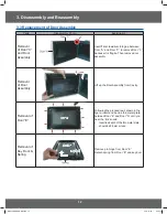
3-5 Replacement of Control Circuit Board
Parts
Explaination Photo
Explaination
Removal of
Control Box
Assembly
CONTROL-BOX
SCREWS
1.
Be sure to ground any static electric
charge in your body and never touch
the control circuit.
2.
Disconnect the connectors from the
control circuit board.
3.
Remove screws securing the control
box assembly.
4.
Remove the screw securing the
ground tail of the keyboard.
Removal of
Ass’y P.C.B
Assembly
and Assy
Key Module
ASSY PCB
ASSY PCB
ASSY
KEY MODULE
TAIL
ASSY
KEY MODULE
TAIL
SCREW
SCREW
SCREW
SCREW
SCREW
SCREW
1.
Remove 2 screws securing the Assy
PCB
2.
Remove Assy Key Module Tail from
the Assy PCB.
3.
Lift up the Assy PCB from the Ass’y
control box.
4.
Remove 6 screws securing the Key
Module PCB
5.
Lift up the Key Module PCB from the
Ass’y control box.
0*0$(065B%:LQGE
Содержание GE73MR
Страница 3: ...3 1 Precaution 0 0 065B LQGE ...


