DTB-H550F
DTB-H550F
DESCRIPTION
ENG-9
ENG-8
D
I
G
I
T
A
L
T
E
R
R
E
S
T
R
I
A
L
H
D
T
V
R
E
C
E
I
V
E
R
ENG
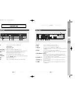
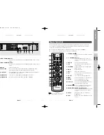
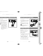
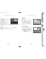
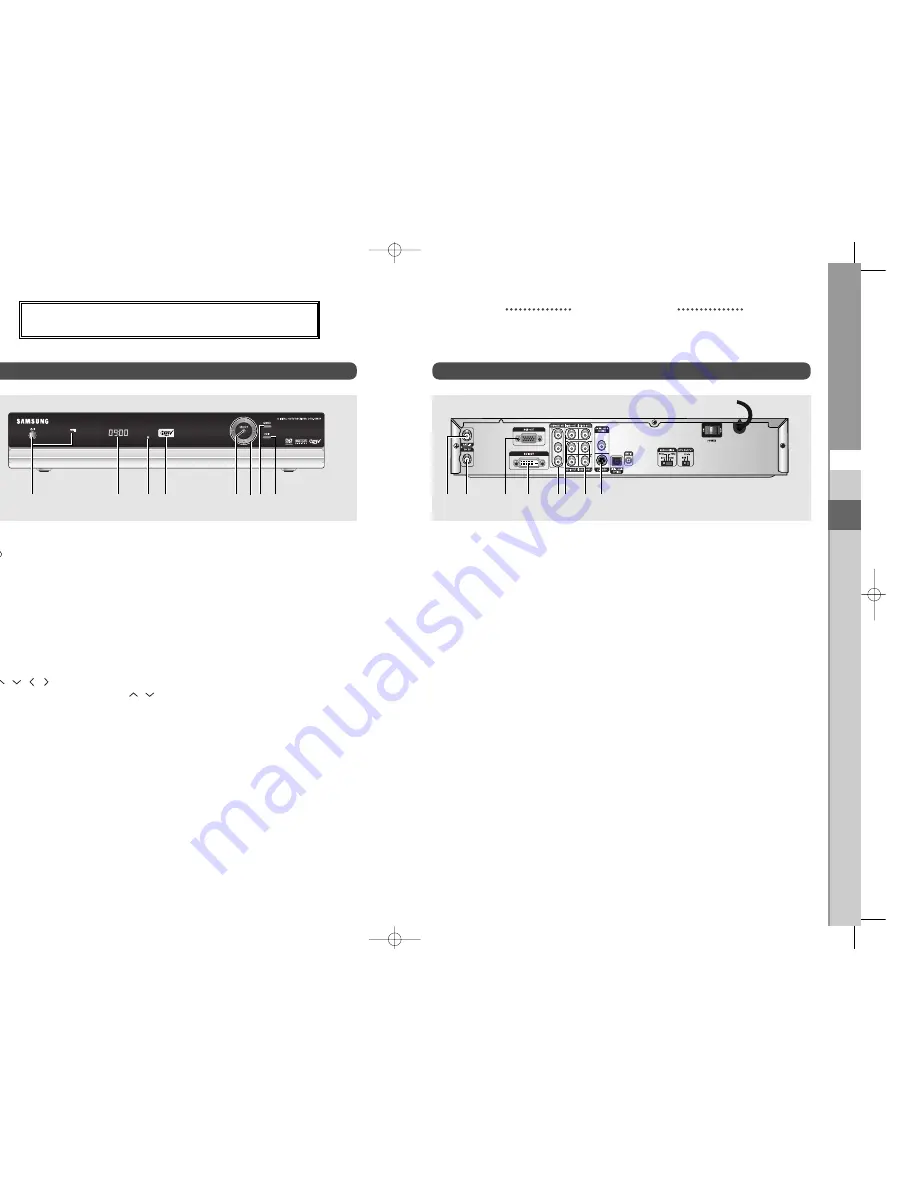
1. ANT.IN
Connect to a digital terrestrial antenna input.
2. TO
TV
Connects a TV or other receiver via a coaxial cable.
3. RGB
OUT
Connect to a TV or monitor through the RGB IN port.
At this time, the DTV OUTPUT switch of the receiver has to be switched
to RGB mode.
4. DVI
OUT
Connect to a TV or monitor through the DVI IN port.
At this time, the DTV OUTPUT switch of the receiver has to be switched
to RGB mode.
5. COMPONENT OUT (YP
B
P
R
)
Connect to a TV, monitor or other external display device through the
Component Video IN (YP
B
P
R
). At this time, the DTV OUTPUT switch of
the receiver has to be switched to YP
B
P
R
mode.
6. VIDEO OUT 1, 2
Connect to a TV, monitor or other external display device through the
Analog Video IN port.
7. AUDIO OUT 1, 2
Connect to a TV, audio receiver, or other external device through the
Analog Audio IN port.
8. S-VIDEO
Connect to a TV, monitor or other external display device through the
S-VIDEO IN port.
Rear Panel
Front Panel
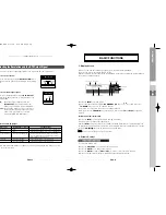
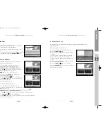
1. / I
Turns the receiver operating or standby mode.
Power Indicator
Operating mode : Blue
Standby mode : Off
2. Display Window
Displays information about digital HDTV receiver.
3. Infrared
Sensor
This is to receive the IR commands from the Remote Control Unit.
4. HDTV
Displays the broadcasting status. When the STB detects a
HD Broadcasting signal, the HDTV logo lights.
5. SELECT
Selects highlighted items on Guide and Menu screens.
6. /
/
/
The arrow keys navigate in the on-screen Guide and Menu system.
Used for CH
/
and VOL +/-.
7. MENU
Displays the main menu.
8. EXIT
Clears on-screen displays and return to TV program viewing.
1
2
4
3
6 7
8
1
3
2
4
5
5
6
7
8
DESCRIPTION
0401 DTB-H550F_ENG 4/1/05 3:18 PM Page 8


