


Samsung Electronics
1-1
1. Precautions
1-1 Safety Precautions
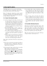
1) Before returning an instrument to the customer,
always make a safety check of the entire instrument,
including, but not limited to, the following items:
(1) Be sure that no built-in protective devices are
defective or have been defeated during servicing.
(1)Protective shields are provided to protect both
the technician and the customer. Correctly replace
all missing protective shields, including any
removed for servicing convenience.
(2)When reinstalling the chassis and/or other as-
sembly in the cabinet, be sure to put back in place
all protective devices, including, but not limited to,
nonmetallic control knobs, insulating fish papers,
adjustment and compartment covers/shields, and
isolation resistor/capacitor networks. Do not oper-
ate this instrument or permit it to be operated with-
out all protective devices correctly installed and
functioning.
(2) Be sure that there are no cabinet openings through
which adults or children might be able to insert
their fingers and contact a hazardous voltage. Such
openings include, but are not limited to, excessive-
ly wide cabinet ventilation slots, and an improper-
ly fitted and/or incorrectly secured cabinet back
cover.
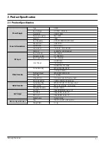
(3) Leakage Current Hot Check-With the instrument
completely reassembled, plug the AC line cord
directly into a 120V AC outlet. (Do not use an iso-
lation transformer during this test.) Use a leakage
current tester or a metering system that complies
with American National Standards institute (ANSI)
C101.1 Leakage Current for Appliances and
Underwriters Laboratories (UL) 1270 (40.7). With
the instrument’s AC switch first in the ON position
and then in the OFF position, measure from a
known earth ground (metal water pipe, conduit,
etc.) to all exposed metal parts of the instrument
(antennas, handle brackets, metal cabinets, screw-
heads, metallic overlays, control shafts, etc.), espe-
cially any exposed metal parts that offer an electri-
cal return path to the chassis.
Any current measured must not exceed 0.5mA.
Reverse the instrument power cord plug in the out-
let and repeat the test. See Fig. 1-1.
Any measurements not within the limits specified
herein indicate a potential shock hazard that must
be eliminated before returning the instrument to
the customer.
Fig. 1-1 AC Leakage Test
(4) Insulation Resistance Test Cold Check-(1) Unplug
the power supply cord and connect a jumper wire
between the two prongs of the plug. (2) Turn on the
power switch of the instrument. (3) Measure the
resistance with an ohmmeter between the
jumpered AC plug and all exposed metallic cabinet
parts on the instrument, such as screwheads,
antenna, control shafts, handle brackets, etc. When
an exposed metallic part has a return path to the
chassis, the reading should be between 1 and 5.2
megohm. When there is no return path to the chas-
sis, the reading must be infinite. If the reading is
not within the limits specified, there is the possibil-
ity of a shock hazard, and the instrument must be
repaired and rechecked before it is returned to the
customer. See Fig. 1-2.
Fig. 1-2 Insulation Resistance Test
DEVICE
UNDER
TEST
(READING SHOULD
NOT BE ABOVE
0.5mA)
LEAKAGE
CURRENT
TESTER
EARTH
GROUND
TEST ALL
EXPOSED METER
SURFACES
ALSO TEST WITH
PLUG REVERSED
(USING AC ADAPTER
PLUG AS REQUIRED)
2-WIRE CORD
Antenna
Terminal
Exposed
Metal Part
ohm
ohmmeter
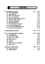
Содержание DSB-S300G
Страница 13: ...3 2 Software Update Samsung Electronics MEMO ...
Страница 19: ...4 6 Disassembly and Reassembly Samsung Electronics MEMO ...
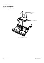
Страница 30: ...Samsung Electronics 6 1 6 Exploded View and Parts List 6 1 Ass y Chassis 6 2 ...
Страница 33: ...Exploded View and Parts List 6 4 Samsung Electronics MEMO ...
Страница 46: ...9 1 9 Wiring Diagram Samsung Electronics ...
Страница 47: ...Wiring Diagram 9 2 MEMO Samsung Electronics ...
Страница 48: ...10 1 10 PCB Diagrams 10 1 Main PCB 10 2 Front PCB 10 3 S M P S PCB 10 2 10 5 10 6 Samsung Electronics ...
Страница 51: ...PCB Diagrams 10 4 Samsung Electronics CONDUCTOR SIDE ...
Страница 52: ...PCB Diagrams 10 5 Samsung Electronics 10 2 Front PCB COMPONENT SIDE CONDUCTOR SIDE ...
Страница 53: ...PCB Diagrams 10 6 Samsung Electronics 10 3 S M P S PCB COMPONENT SIDE ...
Страница 54: ...PCB Diagrams 10 7 Samsung Electronics CONDUCTOR SIDE ...
Страница 55: ...PCB Diagrams 10 8 Samsung Electronics MEMO ...
Страница 69: ...Schematic Diagrams 11 14 Samsung Electronics MEMO ...
Страница 70: ...Samsung Electronics 12 1 12 Operating Instructions ...
Страница 71: ...Operating Instructions 12 2 Samsung Electronics ...
Страница 72: ...Operating Instructions 12 3 Samsung Electronics ...
Страница 73: ...Operating Instructions 12 4 Samsung Electronics ...
Страница 74: ...Operating Instructions 12 5 Samsung Electronics ...
Страница 75: ...Operating Instructions 12 6 Samsung Electronics ...
Страница 97: ...Circuit Operating Descriptions 13 22 Samsung Electronics MEMO ...


