- 48 -
1
2
6
5
7
3
4
14
15
21
17
18
19
20
8
9
10
11
12
13
16
22
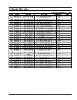
NO.
Parts Number
Part Name
Function and Rule
1
RY601
Main Relay
Lamp, T/T Control
2
RY602
Inrush Relay
Inrush Electric Current Decrease
3
RY603
Power Relay
MW Power Control
4
RY604
Conv. Motor Relay
Conv. Motor Control
5
RY605
Damper Relay
Damper Motor Control
6
RY606
Turn Tabler Motor Relay
Turn Table Motor Control
7
RY607
Fan Motor Relay
Fan Heater Control
8
RY608
Conv. Heater Relay
Conv. Heater Control
9
RY609
Bottom Heater Relay
Bottom Heater Control
10
RY610
Grill Heater Relay
Grill Heater Control
11
RY611
Stream Heater Relay (Steamer Model Option)
Steam Heater Control (Steamer Model Option)
12
RY612
Water Pump Relay (Steamer Model Option)
Water Pump Motor Control (Steamer Model Option)
13
RY613
Live Control Relay
PCB Power Control
14
CN201
Display Module Connector
A Terminal for Connecting with Display Module
15
CN202
On Board Writing Connector
When do micom revision, connect to micom writer. (No connection at normal times)
16
CN501
Door switch , Damper , Humidity Sensing Connector
A Terminal for Connecting with Door Switch , Damper switch, Temperature Sensor
17
CN601
Relay Connector
A Terminal for Connecting with Relay Contact (Load Control)
18
CN602
Power & Relay Connector
A Terminal for Connecting with Power supply , Conv. Motor Relay
19
CN603
Water Pump Relay Connector
A Terminal for Connecting with Water Pump Relay (Steamer Model Option)
20
CN701
"Steam
Heater
Temp
Sensor
/
Weight Sensor Connector"
A Terminal for Connecting with Steam Heater Temp Sensor or Weight Sensor.
21
CN702
"Steam
Heater
Temp
Sensor
/
Water Level Sensor Connector"
A Terminal for Connecting with Steam Heater Temp Sensor or Water Level Switch
22
CN703
Gas Sensor Connector
A Terminal for Connecting with Gas Sensor
6. PCB Diagram
6-1 PCB Diagram
Содержание CP1395E-S
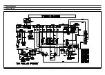
Страница 52: ... 50 7 Wiring Diagram 7 1 Wiring Diagram ...
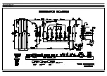
Страница 53: ... 51 8 Schematic Diagram 8 1 Schematic Diagram ...

