- 22 -
Parts
Explaination Photo
Explaination
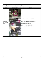
Removal
of Control
Box
Assembly
1. Disconnected Lead wire from Control box Assembly.
2. Remove the 2 screws at both ends holding the Control Box
Assembly.
3. Pull the Control Box Assembly to the left to separate it.
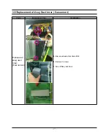
4. Remove 3 screws from PCB Assembly.
5. Remove 10 screws from Assy Display.
3-10 Replacement of Control Circuit Board
Содержание CP1395E-S
Страница 52: ... 50 7 Wiring Diagram 7 1 Wiring Diagram ...
Страница 53: ... 51 8 Schematic Diagram 8 1 Schematic Diagram ...


