Alignment and Adjustments
4-4
Samsung Electronics
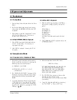
4-3 Other Adjustments
4-3-1 General
1. Usually, a color TV needs only slight touch-
up adjustment upon installation. Check the
basic characteristics such as height, horizontal
and vertical sync and focus.
2. The picture should have good black and white
details. There should be no objectionable
color shading; if color shading is present, per-
form the purity and convergence adjustments
described below.
3. Use the specified test equipment or its equiva-
lent.
4. Correct impedance matching is essential.
5. Avoid overload. Excessive signal from a sweep
generator might overload the front-end of the
TV. When inserting signal markers, do not
allow the marker generator to distort test
results.
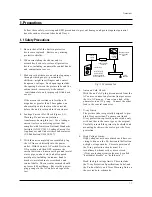
6. Connect the TV only to an AC power source
with voltage and frequency as specified on the
backcover nameplate.
7. Do not attempt to connect or disconnect any
wires while the TV is turned on. Make sure
that the power cord is disconnected before
replacing any parts.
8. To protect against shock hazard, use an isola-
tion transformer.
4-3-2 Automatic Degaussing
A degaussing coil is mounted around the pic-
ture tube, so that external degaussing after
moving the TV should be unnecessary. But
the receiver must be properly degaussed upon
installation.
The degaussing coil operates for about 1 sec-
ond after the power is switched ON. If the set
has been moved or turned in a different direc-
tion, disconnect its AC power for at least 30
minutes.
If the chassis or parts of the cabinet become
magnetized, poor color purity will result. If
this happens, use an external degaussing coil.
Slowly move the degaussing coil around the
faceplate of the picture tube and the sides and
front of the receiver. Slowly withdraw the coil
to a distance of about 6 feet before removing
power.
Содержание CL17M6MQFX/RCL
Страница 2: ...ELECTRONICS Samsung Electronics Co Ltd MAY 2003 Printed in Korea AA82 00654A ...
Страница 6: ...2 4 MEMO ...
Страница 23: ...3 4 Samsung Electronics MEMO ...
Страница 33: ...7 10 Samsung Electronics MEMO ...
Страница 37: ...Schematic Diagrams 10 2 Samsung Electronics 10 2 MAIN 2 4 TP08 TP07 TP11 TP10 TP09 TP07 TP08 TP09 TP10 TP11 ...
Страница 38: ...Schematic Diagrams 10 3 Samsung Electronics 10 3 MAIN 3 4 TP08 TP07 TP07 TP08 Power Line Signal Line ...
Страница 39: ...Schematic Diagrams 10 4 Samsung Electronics 10 4 MAIN 4 4 ...
Страница 45: ...9 2 MEMO ...

