background image

※   In case you want more information about the controllers and accessories, please refer to the Controller and 

Accessory TDB on pvi.Samsung.com site or Global Partner Portal site.

11. Installation

94

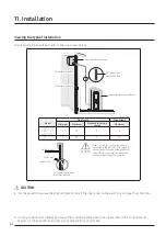
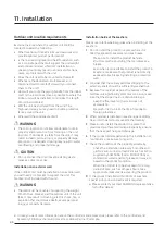
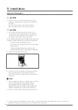
On a wall

  WARNING


The unit must be properly secured to the wall. If the 

unit falls, it may result in crushing, electric shock, 

fire, or explosion that could cause death, severe 

personal injury, or property damage.

1  

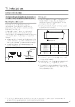
At the selected installation location attach the 

L-bracket to the wall as follows:

 -

Install the bracket as close to the wall as possible.

 -

Insert rubber isolators between the bracket and 

the wall to minimize sound and vibration to the 

structure. Do not fully compress the isolators.

Soft rubber designed to cut off vibration from


rack to wall (not supplied with product)

Soft rubber designed to cut off residual vibration 

from outdoor unit to rack (not supplied with product)

 -

Make sure that the bracket is level.

 -

Use suitable bolts/washers and lock washers.

2  

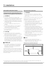
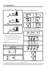
Place the outdoor unit on the bracket, ensuring 

proper clearances and with the arrow on top of the 

unit pointing away from the wall.

3  

Clip the rubber feet to the tabs to minimize sound 

and vibration to the structure.

4  

Level the unit, then use anchor bolts to secure it at 

the four mounting points.

5  

For installations in locations that require seismic or 

hurricane tie downs, comply with local codes.

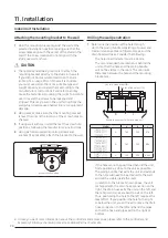
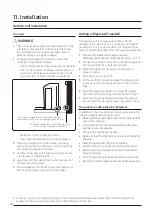
 Adding refrigerant (if needed)

The outdoor unit is charged with sufficient R-32 

refrigerant to support up to a 5 m line set. For lengths 

greater than 5 m, you must add 15 g of refrigerant per 

meter of additional length, after the lines are evacuated.

1  

Calculate the additional refrigerant required: 


Additional grams of R-32 = (Total line set meter − 5) × 15

2  

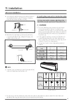
Connect the common hose of the manifold gauge set 

to the inverted R-32 refrigerant cylinder.

3  

Place the refrigerant cylinder on a scale set to 

measure grams.

4  

Open the valve on the tank.

5  

At the manifold connection, bleed the refrigerant to 

remove any air that may be present in the common 

hose.

6  

Open the gauge manifold and charge the system 

with the amount of refrigerant calculated in step 1.

7  

Close the gauge manifold valve, close the valve on 

the refrigerant tank, and remove the common hose.

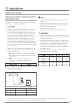
Precautions on adding the R-32 refrigerant

In addition to the conventional charging procedure, the 

following requirements shall be kept.

 •

Make sure that contamination by other refrigerants does 

not occur for charging.

 •

To minimize the amount of refrigerant, keep the hoses 

and lines as short as possible.

 •

The cylinders shall be kept upright.

 •

Make sure that the refrigeration system is earthed before 

charging.

 •

Label the system after charging, if necessary.

 •

Extreme care is required not to overcharge the system.

 •

Before recharging, the pressure shall be checked with 

nitrogen blowing.

 •

After charging, check for leakage before commissioning.

 •

Be sure to check for leakage before leaving the work area.

Outdoor Unit Installation

Содержание AR TX AWKNEU Series

Страница 1: ...Installation RAC forEurope INV R32 50Hz HP Model AR TX AWKNEU Indoor Unit AR TX AWKXEU Outdoor Unit ...

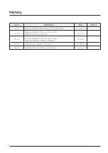
Страница 2: ...urope AR7500 19 10 29 Ver 2 0 Released AR9500T RAC new line up TDB AR4500 AR5500 AR9500 19 11 21 Ver 3 0 Released AR9500T RAC new line up TDB AR4500 AR5500 AR7500 AR9500 19 12 13 Ver 3 1 Updated some specification data 20 02 06 Ver 3 2 Updated the Sound data of Outdoor Unit 20 11 25 ...

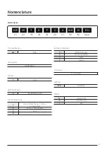
Страница 3: ...eristics C Motion Detect Sensor Wi Fi Tri care Filter E Wi Fi Tri care Filter F Wi Fi H 6 Design Segment A Wind Free GEO C Wind Free AIRISE Y GEO Z AIRISE 7 Version A Z 1 digit 8 Color WK DA White 9 Set N Indoor Unit X Outdoor Unit Set Nomenclature Model Name AR 1 09 2 T 3 X 4 F 5 C 6 A 7 WK 8 N 9 EU Buyer ...

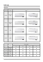
Страница 4: ...orUnit Model Type Design Image AR9500 Wind Free GEO AR7500 Wind Free AIRISE AR5500 GEO AR4500 AIRISE Model Type Design Capacity kW 2 5 3 5 5 0 6 5 AR9500 Wind Free GEO AR7500 Wind Free AIRISE AR5500 GEO AR4500 AIRISE ...

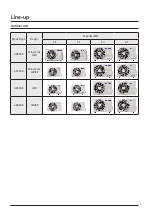
Страница 5: ...5 Model Type Design Capacity kW 2 5 3 5 5 0 6 5 AR9500 Wind Free GEO AR7500 Wind Free AIRISE AR5500 GEO AR4500 AIRISE Line up OutdoorUnit ...

Страница 6: ... 6 Contents 11 Installation 85 ...

Страница 7: ...and settles Areawhere animals mayurinate on the product Ammonia maybe generated Do not usethe indoorunitforpreservation offood items plants equipment and artworks This maycause deterioration oftheirquality Do not install the indoorunit if it has anydrainage problem Forthe multi system this indoorunit can be conncected to an R 32 orR 410Aoutdoorunit Check the type of refrigerant in the outdoorunit ...

Страница 8: ...ectric and drain Compressor condenser outdoor Unit m Model Pipe length Pipe height Minimum Maximum Standard forfactory charge Maximum 07 09 12 3 15 5 8 18 24 3 30 5 15 CAUTION Outdoor Unit Outerwall Indoor Unit Cut insulation to have rainwater drained Make a U trap A on the pipe which is connected to the indoor unit at outerwall and cut the bottom part of the insulation about 10 mm to prevent rain...

Страница 9: ...bed in this manual that are not expressly approved by the manufacturer could void the manufacturer s warranty To determine where to locate the indoor and outdoor units you must survey the entire site and consider many variables The goal is to select locations that comply with all safety precautions while also minimizing the total effort involved Indoorunit location requirements WARNING Do not inst...

Страница 10: ...ting the weight of both the L bracket and the outdoor unit If the unit falls it may result in crushing electric shock fire or explosion that could cause death severe personal injury or property damage Installation Guide at the seashore Make sure to follow below guides when installing at the seashore 1 Do not install the product in a place where it is directly exposed to sea water and sea breeze Ma...

Страница 11: ...at can block the sea breeze and the height and width of the wall should be 1 5 times larger than the size of the outdoor unit You must secure more than 700 mm of space between the protection wall and the outdoor unit for air circulation Minimum clearances forthe outdoorunit Legends Wall Minimum clearance in mm 600 300 Airflow direction Top view Side view Examples forinstalling one outdoorunit Unit...

Страница 12: ...upplied mounting screws and anchors if applicable attach the bracket to the wall Screw Location x 4ea Level Drilling the wall penetration 1 Determine the position of the hole through which the piping bundle consisting of power and communication cables refrigerant pipes and the drain hose will pass Consider the following The hole inner diameter must be 65 mm The recommended hole location is behind ...

Страница 13: ... with the outdoor unit WARNING Do not modify the power cable in any way Doing so may cause electric shock or fire due to poor connection poor insulation or current limit override Make sure to comply with the technical standards of electrical installations and the wiring regulations in the local area This appliance must be properly grounded Do not ground the appliance to a gas pipe plastic water pi...

Страница 14: ... uses the R 32 refrigerant be cautious not to generate a spark bykeeping the following requirements Do not remove the fuseswith poweron Do not disconnect the powerplug from thewall outlet with poweron It is recommended to locate the outlet in a high position Place the cords so that theyare not tangled 2 Tighten the terminal block screw L1 L2 F1 F2 3 In Step 2 2 step 3 you determined the exit posit...

Страница 15: ... the outdoor unit and the ground for installation Ensure that the drained water runs off correctly and safely Allow enough separation distance between the product and the ground 80 mm Estimated snow fall Snow proof hood Ground On the ground 1 Place the outdoor unit in the selected installation location Step 1 1 on page 93 ensuring proper clearances and with the arrow on top of the unit pointing aw...

Страница 16: ...odes Adding refrigerant if needed The outdoor unit is charged with sufficient R 32 refrigerant to support up to a 5 m line set For lengths greater than 5 m you must add 15 g of refrigerant per meter of additional length after the lines are evacuated 1 Calculate the additional refrigerant required Additional grams of R 32 Total line set meter 5 15 2 Connect the common hose of the manifold gauge set...

Страница 17: ... this manual the factory refrigerant charge of the product the additional refrigerant amount charged in the field and the total refrigerant charge on the refrigerant charge label supplied with the product Refrigerant type GWP value R 32 675 GWP Global Warming Potential Calculating tCO e kg x GWP 1000 Indoor unit Outdoor unit Unit Kg tCO e a b c NOTE Factory refrigerant charge of the product see un...

Страница 18: ...Head Office Suwon Korea 129 Samsung Ro Yeongtong Gu Suwon City Gyeonggi Do Korea 16677 Website www samsung com https partnerhub samsung com Email airconditioner samsung com Images and data in this book may subject to change without prior notice ...

Отзывы: