background image

System diagram for DVM Hydro unit / Hydro unit HT

1

3

. Installation

<DVM Hydro unit>

S

Temperature sensor for 

refrigerant gas pipe

Temperature sensor 

for refrigerant 

liquid pipe

Temperature sensor for 

Water inlet pipe

Temperature sensor for 

Water outlet pipe

Water out

Water in

Flow switch

Check valve

Strainer

Strainer

Solenoid valve

Refrigerant gas pipe

Refrigerant liquid pipe

<DVM Hydro unit HT>

R-410A Cycle

R-134a Cycle

Water Cycle

LOW Press. 

Sensor

Compressor

location of the sensor

Pinch pipe

Pinch pipe

Charging port

Charging port

Filter

Filter

Connector  

25.4 mm (1 inch)

Connector  

25.4 mm (1 inch)

4-Way V/V

High Press. 

Sensor

Содержание AM CNB C AA Series

Страница 1: ...Model AM CNB C AA VRF Technical Data Book Hydro Unit for America...

Страница 2: ...History Ver 1 0 Release the VRF Hydro Unit for America 23 06 14 Version Modification Date Remark Ver 1 1 Updated some data 23 08 01 Ver 1 2 Updated some data 23 09 22...

Страница 3: ...ype 5 Product Notation 6 Feature 7 Rating Voltage C 208 230V 60Hz 1 8 Mode H Heat Pump R410A Model Name AM 1 036 2 C 3 N 4 B 5 D 6 C 7 H 8 AA Buyer AM DVM X Outdoor Unit N Indoor Unit B Hydro Unit F C...

Страница 4: ...mmary Table 9 4 Capacity Table 10 5 Capacity correction 15 6 Dimensional Drawing 22 8 Electrical Wiring Diagram 26 30 31 33 35 9 Sound Data 10 Operation range 11 Piping Diagram 12 Hydraulic Performanc...

Страница 5: ...pacity Heating Image Model AM096CNBDCH AA AM144CNBDCH AA AM036CNBDCH AA AM048CNBDCH AA 108 kBtu h 172 kBtu h 40 kBtu h 54 5 kBtu h Hydro Unit HT Capacity Heating Image Model AM072CNBFCB AA 86 kBtu h 5...

Страница 6: ...Method EEV INCLUDED EEV INCLUDED Sound Sound Pressure dB A 27 27 Dimensions Net Weight lbs 64 4 64 4 Shipping Weight lbs 69 0 69 0 Net Dimensions W H D inch 20 4x24 7x13 0 20 4x24 7x13 0 Shipping Dime...

Страница 7: ...V INCLUDED Sound Sound Pressure dB A 28 31 Dimensions Net Weight lbs 75 4 95 2 Shipping Weight lbs 80 0 99 9 Net Dimensions W H D inch 20 4x24 7x13 0 20 4x24 7x13 0 Shipping Dimensions W H D inch 25 7...

Страница 8: ...igerant Type R410A R134a R410A R134a Control Method EEV INCLUDED EEV INCLUDED Sound Sound Pressure dB A 42 42 Dimensions Net Weight lbs 233 7 233 7 Shipping Weight lbs 250 2 250 2 Net Dimensions W H D...

Страница 9: ...44CNBDCH AA 1 2 60 208 230 31 5 50 4 11 7 Hydro Unit HE NOTE FLA Full Load Ampere MCA Minimum Circuit Ampere A MOP Maximum Overcurrent Protective Device A AM048CNBDCH AA 16 0 187 253 Hydro Unit HT Cap...

Страница 10: ...44 019 40 018 32 014 24 011 77 64 94 44 019 40 018 32 014 24 011 86 70 34 44 019 40 018 32 014 24 011 95 75 2 44 019 40 018 32 014 24 011 AM048CNBDCH 4 4 36 42 311 39 922 24 567 16 037 0 5 0 04 44 01...

Страница 11: ...489 77 64 94 116 354 107 482 96 905 64 489 86 70 34 116 354 107 482 96 905 64 489 95 75 2 116 354 107 482 96 905 64 489 AM144CNBDCH 4 4 36 133 415 125 908 77 456 51 865 0 5 0 04 138 533 130 344 86 668...

Страница 12: ...424 1 80 185 4 333 80 185 4 563 80 185 4 802 76 773 5 159 5 81 891 4 287 83 597 4 456 83 597 4 670 80 185 4 996 19 83 597 3 878 85 304 4 084 85 304 4 235 81 891 4 442 27 85 304 3 736 85 304 3 933 85...

Страница 13: ...ty Table 5 1 Combination Capacity index Outdoor Temperature Indoor Temperature DB 68 TC PI DB WB Btu h kW 100 4 6 67 560 7 8 1 0 71 314 7 96 5 3 75 067 8 04 10 9 78 138 7 92 14 12 81 550 7 68 19 18 83...

Страница 14: ...41 39 107 482 6 88 45 43 107 482 6 7 48 46 107 482 6 38 52 50 107 482 6 08 55 54 107 482 5 81 59 57 107 482 5 61 Flowrate Information Flowrate gpm 048 072 T 27 4 1 6 4 T 18 6 1 9 5 T 9 12 2 19 0 Comb...

Страница 15: ...Factor Power Input Correction Factor ODU 7 1 9 5 0 96 1 00 0 94 1 00 4 8 0 92 0 87 Heating Flow rate by T Minimum flow rate of the Hydro unit is 50 of rated flow rate 0 40 0 50 0 60 0 70 0 80 0 90 1...

Страница 16: ...tion Factor ODU 9 5 12 7 0 96 1 00 0 94 1 00 6 3 0 92 0 87 Heating Flow rate by T Minimum flow rate of the Hydro unit is 50 of rated flow rate 0 40 0 50 0 60 0 70 0 80 0 90 1 00 1 10 1 20 5 3 6 3 7 3...

Страница 17: ...put Correction Factor ODU 18 2 24 3 0 96 1 00 0 94 1 00 12 2 0 92 0 87 Heating Flow rate by T Minimum flow rate of the Hydro unit is 50 of rated flow rate 0 40 0 50 0 60 0 70 0 80 0 90 1 00 1 10 1 20...

Страница 18: ...or Power Input Correction Factor ODU 29 7 39 6 0 96 1 00 0 94 1 00 19 8 0 92 0 87 Heating Flow rate by T Minimum flow rate of the Hydro unit is 50 of rated flow rate 0 40 0 50 0 60 0 70 0 80 0 90 1 00...

Страница 19: ...B WB 68 86 104 113 4 4 4 1 00 1 30 1 12 1 00 5 4 5 1 07 1 36 1 21 1 03 14 13 1 1 13 1 42 1 29 1 05 23 21 9 1 20 1 31 1 37 0 99 32 30 7 1 11 1 21 1 27 0 93 41 24 6 1 01 1 11 1 16 0 87 45 42 8 0 97 1 06...

Страница 20: ...door temperature F Capacity coefficient Capacity coefficient of outdoor unit on defrost operation Corrected Heating Capacity heating capacity x Capacity coefficient 2 Power input of hydro unit HT duri...

Страница 21: ...9 57 107 482 5 61 Hydro Unit HT 5 Capacity correction 8TON DVM S TDB Heat Capacity Table Example Combination 8TON DVM S 4TON HT X 2ea Outdoor 41 F DB EW LW 131 F 149 F 1 Defrosting correction factor O...

Страница 22: ...Liquid Pipe Connection 15 88 5 8 Gas Pipe Connection 9 52 3 8 Communication Wiring Conduits Power supply conduit Water outlet pipe Water inlet pipe AM036CNBDCH AA AM048CNBDCH AA AM096CNBDCH AA AM144C...

Страница 23: ...Drawing Hydro Unit HT Unit mm inch No Name Description 1 Liquid pipe connection 2 Gas pipe connection 3 4 9 52 3 8 15 88 5 8 Power supply conduit Communication Wiring Conduits 5 6 Water outlet pipe Wa...

Страница 24: ...7 Center of Gravity Hydro Unit HE Unit mm inch 284 9 11 3 16 185 2 7 5 16 321 8 12 11 16...

Страница 25: ...7 Center of Gravity Hydro Unit HT Unit mm inch 185 4 7 5 16 593 3 23 3 8 242 3 9 9 16...

Страница 26: ...ectronic expansion valve 8 Electrical wiring diagram AM036CNBDCH AA AM048CNBDCH AA AM096CNBDCH AA AM144CNBDCH AA NOTE This wiring diagram applies only to the Indoor unit Symbols show as follow BLK bla...

Страница 27: ...10Kohm 4 WAY VALVE Solenoid valve 4 Way valve WATER OUT TEMP Thermistor WATER OUT_10Kohm FH152 FUSE INV PCB EVA IN TEMP Thermistor EVA IN_10Kohm 250V 40A FUSE EMI PCB EVA OUT TEMP Thermistor EVA OUT_1...

Страница 28: ...NC 30 25 NC 30 25 20 Heating NC 25 20 NC 25 20 15 NC 20 Hearing threshold 15 NC 20 15 10 NC 15 0 NC 15 0 5 5 0 0 0 0 63 125 250 500 1000 2000 4000 8000 63 125 250 500 1000 2000 4000 8000 Octave Band...

Страница 29: ...essure 0 dB 20 Pa 9 Sound Data Hydro Unit HT 90 90 85 85 80 80 75 75 70 70 65 65 60 NC 70 60 Heating 55 NC 60 55 50 NC 55 50 45 NC 50 45 40 NC 45 40 35 NC 40 35 30 NC 35 30 25 NC 30 25 20 NC 25 20 NC...

Страница 30: ...r to outdoor unit technical data book for outdoor unit operating range 1 Heating Ta Ambient temperature LWT Leaving water temperature Hydro Unit HT 23 109 Continuous Operation range Warming up operati...

Страница 31: ...Outlet Water Outlet Temp Sensor THERMOSTAT Water Outlet T2 T_WO Temp Sensor T 4 Ref Gas Bypass Valve Water Inlet for Defrost B Temp Sensor Flow Switch T 3 E Plate Heat Exchanger R410A water PHE1 Eva...

Страница 32: ...134a E_M 4Way Valve Plate Heat V_4W Exchanger Entering Water R134a water Temp Sensor PHE1 T_EW Leaving Water Low Pressure Temp Sensor Sensor LPS High Pressure Sensor HPS Comp Top Discharge Temp Sensor...

Страница 33: ...A Water flow rate GPM Pressure drop from heat exchanger psi 5 3 0 9 7 1 1 5 9 2 10 8 2 9 12 7 3 8 Pressure drop from heat exchanger psi 7 3 6 5 0 0 0 7 1 5 2 2 2 9 3 6 4 4 5 1 5 8 26 4 21 1 15 9 10 6...

Страница 34: ...Pressure drop from heat exchanger psi 3 2 0 2 4 0 0 2 5 3 0 4 6 6 0 6 7 9 0 8 9 2 1 0 10 6 1 3 13 2 1 9 15 9 2 7 18 5 3 6 19 0 3 8 Water ow rate GPM Pressure drop from heat exchanger psi 0 00 0 50 1 0...

Страница 35: ...es between the DVM Hydro unit Hydro unit HT and outdoor unit within allowable distance f Do not install this product in a place where it may corrode f Install the DVM Hydro unit Hydro unit HT power an...

Страница 36: ...wall prevent unit vibration from transmitting to nearby walls with cushioning materials etc Unit mm inch Hydro unit HT Unit mm inch When stacking Hydro units 100 3 9 400 15 7 600 23 6 100 3 9 100 3 9...

Страница 37: ...bolt nut and washer The bearing force has to be over 3 5 kN 786 8 lb f 5 Fix the DVM Hydro unit Hydro unit HT firmly with 4 foundation bolts 6 When concrete construction for DVM Hydro unit Hydro unit...

Страница 38: ...lat and level Adjust the level support keeping at least 10 mm 0 4 inch from the bottom of the level support to the bottom of the fixed bracket Place the DVM Hydro unit HT on the base and fix it with a...

Страница 39: ...mm 2 0 inch 30 N m 22 1 lbf ft 340 13 4 333 13 1 330 13 0 16 0 6 599 23 6 365 14 4 626 24 6 27 1 1 120 47 2 67 23 6 Water outlet pipe Communication cable Gas pipe Liquid pipe Power cable Water inlet...

Страница 40: ...106 4 2 244 9 6 367 14 4 466 18 3 1210 47 6 365 14 4 518 20 4 Communication cable Power cable Gas pipe Liquid pipe Water outlet pipe Water inlet pipe Model of the Hydro unit AM CNBF Refrigerant side...

Страница 41: ...gerant container is painted in pink Model name of DVM Hydro unit AM036CNBDCH AM048CNBDCH AM048CNBFCB AM072CNBFCB AM096CNBDCH AM144CNBDCH Amount of additional refrigerant 0 6 kg 1 3 lb 0 7 kg 1 5 lb 1...

Страница 42: ...of these oils Torque wrench Connect flare nut with pipe Compatible Pipe bender Pipe bending Nitrogen gas Air tightness test Inhibition of oxidation Welder Pipe welding Manifold gauge Air tightness te...

Страница 43: ...n f Use the flare nut supplied with the product If other flare nuts are used it can cause refrigerant leakage Exposure place Exposure time Sealing type Outdoor Longer than one month Pipe pinch Shorter...

Страница 44: ...razing the pipes oxide may form inside the pipe and can cause damage to the important parts such as compressor and valves etc Adjust the flow rate of the nitrogen flushing with a pressure regulator to...

Страница 45: ...without cutting you may get injured by the refrigerant within the pipe CAUTION 1 Remove the copper cap of the refrigerant pipe and eliminate the sludge or foreign substances on the brazed part and the...

Страница 46: ...r selecting the refrigerant pipes which meet the standard material thickness Make sure to use liquid refrigerant when charging the refrigerant because the used refrigerant is a blended refrigerant DVM...

Страница 47: ...the condition is in high humidity use one grade thicker Pipe Outer diameter Insulator Remarks General 30 C 86 F 85 Highhumidity 30 C 86 F over85 EPDM NBR mm inch mm inch mm inch Liquid pipe 6 35 9 52...

Страница 48: ...e pipe and install the drain pipe horizontally with a slope of 2 or more to prevent water from flowing backwards For smooth drainage install an air vent that is open to air Insulate the drain pipe and...

Страница 49: ...o unit HT Water pipe Insulation Over 80 mm Finishing tape On site installation Ball valve Used as cleaning hole Water out Water in Buffer tank Mixing tank Cleaning device Hydro unit Heat exchanger on...

Страница 50: ...0 50 min 0 13 2 gal min 0 100 C 0 212 F 0 1 Mpa 0 145 psi 0 6 m3 h 158 5gal h Condition 0 15MPa 21 8psi 23 min 6 1 gal min NPT 1 15 A AM072CNBFCB 0 100 min 0 26 4 gal min 36 min 9 5 gal min AM036CNBD...

Страница 51: ...ydro unit HT is under 0 C 32 F When water pipe circuit freezes it will cause damage to the plate type heat exchanger and therefore preventive measure must be taken according to the situation a Drain r...

Страница 52: ...oblem to it 13 Make sure that water quality within the water pipe meets the standard of cooling water quality for refrigerating and air conditioning equipment Water containing high level of foreign su...

Страница 53: ...connected to the outdoor unit after flushing cleaning foreign substances in water pipe is completed Check that air is vented from the water pipe and circulation amount is secured before opening the se...

Страница 54: ...n of the product clean the strainer regularly more than once a year Connecting powerand communication cable Specification of electric wires Indoor unit Power supply MCCB ELB Power cable Earth cable Co...

Страница 55: ...nstalled 10 A Indoor unit 10 20 m 65 6 ft 10 m 32 8 ft 0 m 0 ft 9 A 1 A 100 m 328 1 ft Indoor unit 2 Indoor unit 1 ELCB MCCB ELB Or f Apply following equation n k 1 Coef 35 6 Lk ik 10 of input voltage...

Страница 56: ...Communication cable Wired remote controller Wired remote controller Exclusive wired remote controller Wired remote controller MCCB ELB ELCB or DVM Hydro unit MCCB ELB ELCB or 1 Phase Overall system c...

Страница 57: ...rom one indoor DVM Hydro unit Hydro unit HT to another It may cause communication error Do not divide power cable multiple times from one Hydro unit HT to another DVM Hydro unit HT can get a damage Po...

Страница 58: ...t side of the outdoor unit Wires must be installed after putting them in separate conduit tubes Fix the conduit at the cable outlet using a conduit adapter Main PCB Wired remote controller wiring DVM...

Страница 59: ...PVC compound When the cable tube is installed outdoor and exposed to outside so there are risk of damage to the cable tube and extra waterproof is needed 13 Installation Power and communication wirin...

Страница 60: ...M CNBD AM CNBF V1 V2 L N Power cable 1 Phase AC 208 230 V Wired remote controller Outdoor unit Communication cable 1 L 2 N N L F1 F2 V1 V2 F3 F4 L N DVM Hydro unit Hydro unit HT cable tie Power cable...

Страница 61: ...13 Installation Wiring diagram for connecting 2 wired remote controllers AM CNBD AM CNBF V1 V2 L N Wired remote controller Sub Wired remote controller Main...

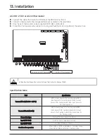
Страница 62: ...the screws on the terminal board Tighten the terminal screws by applying rated torque value If the terminal is loose arc heat may occur and cause fire and if the terminal is connected too firmly termi...

Страница 63: ...check Alarm Water pump Booster heater 3Way valve 1 2Way valve 3Way valve 2 AC 24 V Thermostat 208 230 V Thermostat Wired remote controller Outdoor unit communication cable Water IN OUT Hydro unit Wate...

Страница 64: ...8 3 4 Input DC 20 mA L Solar pump 13 14 5 6 Contact input 10 mA M External control 16 17 7 8 Contact input 1 mA N Smart grid 19 20 9 10 Input DC 1 mA O Communication cable RS485 F1 F2 Input Output DC...

Страница 65: ...Optional B21 B22 AC 208 230 Thermostat 2 Input thermostat signal for heating AC 208 230 V Optional B23 B24 AC24 Thermostat 1 Input thermostat signal for cooling AC 24V Optional B25 B26 AC24 Thermosta...

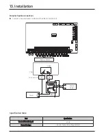
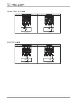
Страница 66: ...al block CAUTION Terminal of this product is forwater pump and the maximum allowable current is 0 5 A Specification table V1 V2 L N Water pump L N M C Terminal board B5 Pump Power B6 PCB Relay Part Sp...

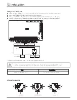
Страница 67: ...booster heater to B7 B8 of the PBA terminal block Specification table V1 V2 L N Booster heater L N M C Terminal board B7 Booster heater Power B8 PCB Relay Part Specification Terminal block Output B7 B...

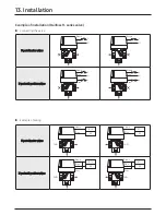
Страница 68: ...3 Way valve 2 When the valve is connected to B12 and B14 its direction should be tank side CAUTION Before completing installation of 3Way valve check the opening direction of the port Allowed connecti...

Страница 69: ...er valves AB A B L N Blue Brown AB A B L N Blue Brown 3 port mid position valves AB A B L L N Blue Grey Brown AB A B L L N Blue Grey Brown 3 port diverter valves B10 B9 AB A B DHW Blue Brown B11 B9 AB...

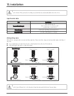
Страница 70: ...terminal block 2Way valve is interlocked with 3Way valve 1 V1 V2 L N AC 220 240 V Defrost signal contact V1 V2 L N 2Way valve Connect B12 B13 3 Way valve 2 of the terminal block to use the defrost mo...

Страница 71: ...fix it with a cable tie Initial setting of the valve is closed no flow 13 Installation Part Specification Terminal block Output B15 Output power N B16 Output power L switch type B17 Output power L sw...

Страница 72: ...30 V Thermostat AC 24 V Thermostat Part Specification Terminal block AC 208 230 V B19 Output power L for cooling mode B20 Input power N for cooling mode B21 Output power L for heating mode B22 Input p...

Страница 73: ...AC 208 230 V thermostat AC 24 V thermostat 13 Installation Cooling mode Not use Heating mode Thermostat N L Thermostat N L Cooling mode Not use Heating mode Thermostat N L Thermostat N L...

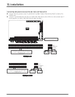
Страница 74: ...east one of them should be connected directly to the temperature sensor 13 Installation SENSOR SET TERMINAL BLOCK SMPS 24V 7 8 SENSOR SET TERMINAL BLOCK SMPS 24V 3 4 V1 V2 L N Flow switch Temperature...

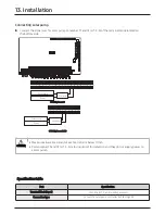
Страница 75: ...5 6 is for input port for detection and they do not supply power to a solar pump 13 Installation V1 V2 L N Controller Power Solar pump 1 2 3 4 5 6 7 8 9 10 11 12 13 14 15 16 17 18 19 20 Controller Pow...

Страница 76: ...Temperature sensor for Water outlet pipe Water out Water in Flow switch Check valve Strainer Strainer Solenoid valve Refrigerant gas pipe Refrigerant liquid pipe DVM Hydro unit HT R 410A Cycle R 134a...

Страница 77: ...Korea 129 Samsung Ro Yeongtong Gu Suwon City Gyeonggi Do Korea 16677 Website www samsung com https partnerhub samsung com Email airconditioner samsung com Images and data in this book may subject to...

Отзывы: