background image

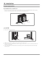
Refrigerant pipe installation

10. Installation

WARNING

When installing, make sure there is no leakage. When collecting the refrigerant, stop the compressor first

before removing the connection pipe. If the refrigerant pipe is not properly connected and the compressor

works with the service valve open, the pipe inhales the air and it makes the pressure inside of the refrigerant

cycle abnormally high which may lead to explosion and injury.

Refrigerant pipe work

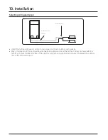
The length of refrigerant pipe should be as short as possible and the height difference between an indoor and

outdoor unit should be minimized.

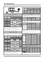
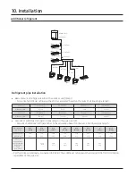
Piping work must be done within allowable piping length, height difference, and the allowable length after

branching.

The pressure of the R-410A is high. Use only certified refrigerant pipe and follow the installation method.

After installing the pipes, calculate the total length of the pipe to check if additional refrigerant is needed.

When


you need to charge the additional refrigerant, make sure to use R-410A refrigerant.

Use clean refrigerant pipe and there shouldn’t be any harmful ion, oxide, dust, iron content or moisture inside

pipe.

Use tools and accessories that fit on R-410A only

.

 Installation process/

Compatibility with 

Tool

purpose 

conventional tool

Pipe cutter

Pipe cutting

Compatible

Flaring tool

Pipe flaring

Apply 

Exclusive ether oil, ester oil, 

alkali benzene oil or synthetic 

oil 

Refrigerant 

refrigerant 

machine oil

Refrigerant 

oil on flared 

pipe 

part

installation

Connect 

Torque 

flare nut 

wrench

with pipe

Pipe 

Pipe bender 

bending

Prevent 

Compatible

Nitrogen 

oxidation 

gas

Air 

within the 

tightness 

pipe

test

Pipe 

Welder

welding

Manifold 

Air 

Vacuuming, 

Compatible

gage

tightness 

charging 

test ~ 

refrigerant 

Need exclusive one since there 

is risk of refrigerant leakage or 

inflow of impurities

Refrigerant 

additional 

and 

charging 

refrigerant 

checking 

hose

charging

operation

Compatible (Use products which 

contain the check valve to 

prevent the oil from flowing 

backward into the outdoor unit.) 

Use the one that can 

be vacuumed up to 

-100.7kpa(5Torr).

Vacuum 

Pipe drying

pump

Scale for 

refrigerant 

Refrigerant charging

Compatible

charging

Need exclusive one 

(Ones used for R-134a is 

compatible)

Gas leak 

Gas leak test

detector

Flare nut

Must use the flare nut equipped with the product.

Содержание AM BXVGFH/AA Series

Страница 1: ...Model AM BXVGFH AA AM BXVGJH AA VRF Technical Data Book DVM S2 for America R410A 60Hz HP ...

Страница 2: ...History Version Modification Date Remark Ver 1 0 Release DVM S2 HP TDB for America 22 02 23 Ver 1 1 Modified some errors 22 09 26 ...

Страница 3: ...ture 1 V Inverter 6 Feature 2 A Standard General Temp Module H High EER Low Temp Module G High EER General Temp Module D Standard General Temp Non Module 7 Rating Voltage 8 Mode H Heat Pump R Heat Recovery OutdoorUnit Model Name 1 2 3 4 5 6 7 8 Buyer 240 AA B F kBtu h 3 digits F J 3Ø 3 208 230V 60Hz 3Ø 3 460V 60Hz ...

Страница 4: ...lligent features make installation and maintenance easier and more cost effective Perfectly compatible with WindFree Active Frequency Drive 10Hz Enjoy continuous comfort and avoid wasting energy Active Frequency Drive 10Hz technology enables the compressor to precisely control a small amount of refrigerant So it maintains a more consistent temperature and is compatible with Samsung s WindFree Cool...

Страница 5: ... Triple Profile Scroll and efficient Optimal Discharge Superheat DSH Control technology Samsung circulates 14 400cc sec refrigerant 90cc displacement volume x 160rps revolutions per second while Company A circulates 12 480cc sec 96cc x 130rps Company B circulates 14 080cc sec 88cc x 160rps and Company C circulates 12 320cc sec 88cc x 140rps More powerful performance less space Based on internal te...

Страница 6: ...re Combination Ratio 7 2 Specification 15 3 Electric Characteristics 39 4 Dimensional Drawing 40 5 Center of Gravity 43 6 Electrical Wiring Diagrams 46 7 Sound Data 51 8 Operation Range 59 9 Piping Diagram 61 10 Installation 65 11 AHRI Data 100 ...

Страница 7: ... can connect maximum 64 indoor units to the outdoor unit Maximum quantity of connectable indoor unit is set to 64 since outdoor unit only support up to 64 communication address Indoor unit address can be assigned from 0 63 If the indoor unit address was assigned from 64 79 E201 error will occur Maximum 32 Wall mount type indoor units with EEV AM NQD AM NVD can be connected NOTE SystemModel Capacit...

Страница 8: ...an connect maximum 64 indoor units to the outdoor unit Maximum quantity of connectable indoor unit is set to 64 since outdoor unit only support up to 64 communication address Indoor unit address can be assigned from 0 63 If the indoor unit address was assigned from 64 79 E201 error will occur Maximum 32 Wall mount type indoor units with EEV AM NQD AM NVD can be connected NOTE SystemModel Capacity ...

Страница 9: ...VGFH AA AM336BXVGFH AA AM360BXVGFH AA 8 10 12 14 AM096BXVGFH AA AM120BXVGFH AA AM144BXVGFH AA AM168BXVGFH AA 32 34 36 AM384BXVGFH AA AM408BXVGFH AA AM432BXVGFH AA 16 18 20 AM192BXVGFH AA AM216BXVGFH AA AM240BXVGFH AA 38 40 AM456BXVGFH AA AM480BXVGFH AA 22 AM264BXVGFH AA External Appearance 1 Combination Table Outdoor units ...

Страница 10: ...JH AA AM336BXVGJH AA AM360BXVGJH AA 8 10 12 14 AM096BXVGJH AA AM120BXVGJH AA AM144BXVGJH AA AM168BXVGJH AA 32 34 36 AM384BXVGJH AA AM408BXVGJH AA AM432BXVGJH AA 16 18 20 AM192BXVGJH AA AM216BXVGJH AA AM240BXVGJH AA 38 40 AM456BXVGJH AA AM480BXVGJH AA 22 AM264BXVGJH AA External Appearance 1 Combination Table Outdoor units ...

Страница 11: ... necessaryto design a combination ratio exceeding130 the following conditions must be complied with Design Selection Procedure Determine DVM Design Condition Design temperature Calculate cooling and heating loads Zone peak loads System Peak load Power supply piping length and level difference Select indoorunit foreach zone Max capacity at design condition should be greater than Zone Peak Load Sele...

Страница 12: ...ne Peak Loads at 14 00 61 0kW When a system combination ratio is over130 a max system capacity is the same as the published capacity in TDB capacity table at the combination ratio of 130 NOTE Cooling Operation Only When only cooling operation is used CR is allowed up to 180 if the Max Capacity of outdoor unit is greater than System Peak Load Block load as shown table 2 Outdoor unit All capacities ...

Страница 13: ... in both cooling heating mode 100 Sum of nominal capacity of indoor units The Minimum Operation Ratio should be determined during the project design stage using Fig 2 Fig 2 Allowable CR with respect to indoor unit type as operation ratio increases Combination Ratio Connection Ratio Outdoor unit All capacities of H P H R Single Dual and Triple Module Systems Indoor unit All indoor unit types except...

Страница 14: ...e including abnormal noise that arises during heating operation due solely to the operation rate being lower than the designated combination ratio shown in Fig 2 Please contact your local Samsung representative for further details if the project requires you to design the project with a connection ratio greater than 130 NOTE Combination Ratio Connection Ratio Type of indoor unit Limited by CR130 1...

Страница 15: ...2 Inverter Scroll x 2 Output kW x n 4 60 x 1 4 60 x 2 4 60 x 2 Model Name DS2GT7046EV x 1 DS2GT7046EV x 2 DS2GT7046EV x 2 Oil Type PVE PVE PVE Initial charge cc x n 900 x 1 900 x 2 900 x 2 fl oz x n 30 4 x 1 30 4 x 2 30 4 x 2 Fan Type Propeller Propeller Propeller Dischargedirection Top Top Top Quantity EA 1 2 2 AirFlow Rate CFM min 5 580 158 9 924 281 9 924 281 ExternalStatic Pressure Max Aq 11 1...

Страница 16: ...t capacity over the rated outdoor unit capacity is 50 130 Combination ratio of up to 184 is allowed depending on operation mode minimum operation ratio and connected indoor unit models DVM Pro 2 design software supports designing over 130 based on system design Refer to the Design Procedure Combination Ratio section of this document for details 3 If outdoor unit is located in a higher position tha...

Страница 17: ... Inverter Scroll x 2 Output kW x n 4 60 x 2 6 45 x 2 6 45 x 2 Model Name DS2GT7046EV x 2 DS4GT5066EV x 2 DS4GT5066EV x 2 Oil Type PVE PVE PVE Initial charge cc x n 900 x 2 1 100 x 2 1 100 x 2 fl oz x n 30 4 x 2 37 2 x 2 37 2 x 2 Fan Type Propeller Propeller Propeller Dischargedirection Top Top Top Quantity EA 2 2 2 AirFlow Rate CFM min 10 171 288 10 665 302 12 855 364 ExternalStatic Pressure Max A...

Страница 18: ...the total rated indoor unit capacity over the rated outdoor unit capacity is 50 130 Combination ratio of up to 184 is allowed depending on operation mode minimum operation ratio and connected indoor unit models DVM Pro 2 design software supports designing over 130 based on system design Refer to the Design Procedure Combination Ratio section of this document for details 3 If outdoor unit is locate...

Страница 19: ...5 x 2 6 45 x 2 4 60 x 2 x 1 6 45 x 2 x 1 Model Name DS4GT5066EV x 2 DS4GT5066EV x 2 DS2GT7046EV x 2 x 1 DS4GT5066EV x 2 x 1 Oil Type PVE PVE PVE Initial charge cc x n 1 100 x 2 1 100 x 2 900 x 2 x 1 1 100 x 2 x 1 fl oz x n 37 2 x 2 37 2 x 2 30 4 x 2 x 1 37 2 x 2 x 1 Fan Type Propeller Propeller Propeller Dischargedirection Top Top Top Quantity EA 2 2 4 AirFlow Rate CFM min 13 314 377 13 773 390 9 ...

Страница 20: ...ure 47 DB 43 WB 2 The standard allowed combination ratio of the total rated indoor unit capacity over the rated outdoor unit capacity is 50 130 Combination ratio of up to 184 is allowed depending on operation mode minimum operation ratio and connected indoor unit models DVM Pro 2 design software supports designing over 130 based on system design Refer to the Design Procedure Combination Ratio sect...

Страница 21: ... x 1 DS4GT5066EV x 2 x 1 DS2GT7046EV x 2 x 1 DS4GT5066EV x 2 x 1 DS2GT7046EV x 2 x 1 DS4GT5066EV x 2 x 1 Oil Type PVE PVE PVE Initial charge cc x n 900 x 2 x 1 1 100 x 2 x 1 900 x 2 x 1 1 100 x 2 x 1 900 x 2 x 1 1 100 x 2 x 1 fl oz x n 30 4 x 2 x 1 37 2 x 2 x 1 30 4 x 2 x 1 37 2 x 2 x 1 30 4 x 2 x 1 37 2 x 2 x 1 Fan Type Propeller Propeller Propeller Dischargedirection Top Top Top Quantity EA 4 4 ...

Страница 22: ... NOTE Specification may be subject to change without prior notice 1 Nominal capacities are based on Equivalent refrigerant piping 25ft Level differences 0ft Cooling Indoor temperature 80 DB 67 WB Outdoor temperature 95 DB 75 WB Heating Indoor temperature 70 DB 60 WB Outdoor temperature 47 DB 43 WB 2 The standard allowed combination ratio of the total rated indoor unit capacity over the rated outdo...

Страница 23: ...1 6 45 x 2 x 2 6 45 x 2 x 2 Model Name DS2GT7046EV x 2 x 1 DS4GT5066EV x 2 x 1 DS4GT5066EV x 2 x 2 DS4GT5066EV x 2 x 2 Oil Type PVE PVE PVE Initial charge cc x n 900 x 2 x 1 1 100 x 2 x 1 1 100 x 2 x 2 1 100 x 2 x 2 fl oz x n 30 4 x 2 x 1 37 2 x 2 x 1 37 2 x 2 x 2 37 2 x 2 x 2 Fan Type Propeller Propeller Propeller Dischargedirection Top Top Top Quantity EA 4 4 4 AirFlow Rate CFM min 9 924x 1 13 7...

Страница 24: ...25ft Level differences 0ft Cooling Indoor temperature 80 DB 67 WB Outdoor temperature 95 DB 75 WB Heating Indoor temperature 70 DB 60 WB Outdoor temperature 47 DB 43 WB 2 The standard allowed combination ratio of the total rated indoor unit capacity over the rated outdoor unit capacity is 50 130 Combination ratio of up to 184 is allowed depending on operation mode minimum operation ratio and conne...

Страница 25: ... x 2 Model Name DS4GT5066EV x 2 x 2 DS2GT7046EV x 2 x 2 DS4GT5066EV x 2 x 1 DS2GT7046EV x 2 x 1 DS4GT5066EV x 2 x 2 Oil Type PVE PVE PVE Initial charge cc x n 1 100 x 2 x 2 900 x 2 x 2 1 100 x 2 x 1 900 x 2 x 1 1 100 x 2 x 2 fl oz x n 37 2 x 2 x 2 30 4 x 2 x 2 37 2 x 2 x 1 30 4 x 2 x 1 37 2 x 2 x 2 Fan Type Propeller Propeller Propeller Dischargedirection Top Top Top Quantity EA 4 6 6 AirFlow Rate...

Страница 26: ...cation may be subject to change without prior notice 1 Nominal capacities are based on Equivalent refrigerant piping 25ft Level differences 0ft Cooling Indoor temperature 80 DB 67 WB Outdoor temperature 95 DB 75 WB Heating Indoor temperature 70 DB 60 WB Outdoor temperature 47 DB 43 WB 2 The standard allowed combination ratio of the total rated indoor unit capacity over the rated outdoor unit capac...

Страница 27: ...er Scroll x 2 Output kW x n 4 60 x 1 4 60 x 2 4 60 x 2 Model Name DS2GR7046FV x 1 DS2GR7046FV x 2 DS2GR7046FV x 2 Oil Type PVE PVE PVE Initial charge cc x n 900 x 1 900 x 2 900 x 2 fl oz x n 30 4 x 1 30 4 x 2 30 4 x 2 Fan Type Propeller Propeller Propeller Dischargedirection Top Top Top Quantity EA 1 2 2 AirFlow Rate CFM min 5 580 158 9 924 281 9 924 281 ExternalStatic Pressure Max Aq 11 11 11 Pa ...

Страница 28: ...otal rated indoor unit capacity over the rated outdoor unit capacity is 50 130 Combination ratio of up to 184 is allowed depending on operation mode minimum operation ratio and connected indoor unit models DVM Pro 2 design software supports designing over 130 based on system design Refer to the Design Procedure Combination Ratio section of this document for details 3 If outdoor unit is located in ...

Страница 29: ...r Scroll x 2 Output kW x n 4 60 x 2 6 67 x 2 6 67 x 2 Model Name DS2GR7046FV x 2 DS4GR7066FV x 2 DS4GR7066FV x 2 Oil Type PVE PVE PVE Initial charge cc x n 900 x 2 1 100 x 2 1 100 x 2 fl oz x n 30 4 x 2 37 2 x 2 37 2 x 2 Fan Type Propeller Propeller Propeller Dischargedirection Top Top Top Quantity EA 2 2 2 AirFlow Rate CFM min 10 171 288 10 665 302 12 855 364 ExternalStatic Pressure Max Aq 11 11 ...

Страница 30: ...e total rated indoor unit capacity over the rated outdoor unit capacity is 50 130 Combination ratio of up to 184 is allowed depending on operation mode minimum operation ratio and connected indoor unit models DVM Pro 2 design software supports designing over 130 based on system design Refer to the Design Procedure Combination Ratio section of this document for details 3 If outdoor unit is located ...

Страница 31: ...67 x 2 4 60 x 2 x 1 6 67 x 2 x 1 Model Name DS4GR7066FV x 2 DS4GR7066FV x 2 DS2GR7046FV x 2 x 1 DS4GR7066FV x 2 x 1 Oil Type PVE PVE PVE Initial charge cc x n 1 100 x 2 1 100 x 2 900 x 2 x 1 1 100 x 2 x 1 fl oz x n 37 2 x 2 37 2 x 2 30 4 x 2 x 1 37 2 x 2 x 1 Fan Type Propeller Propeller Propeller Dischargedirection Top Top Top Quantity EA 2 2 4 AirFlow Rate CFM min 13 314 377 13 773 390 9 924x 1 1...

Страница 32: ...e 47 DB 43 WB 2 The standard allowed combination ratio of the total rated indoor unit capacity over the rated outdoor unit capacity is 50 130 Combination ratio of up to 184 is allowed depending on operation mode minimum operation ratio and connected indoor unit models DVM Pro 2 design software supports designing over 130 based on system design Refer to the Design Procedure Combination Ratio sectio...

Страница 33: ...GR7066FV x 2 x 1 DS2GR7046FV x 2 x 1 DS4GR7066FV x 2 x 1 DS2GR7046FV x 2 x 1 DS4GR7066FV x 2 x 1 Oil Type PVE PVE PVE Initial charge cc x n 900 x 2 x 1 1 100 x 2 x 1 900 x 2 x 1 1 100 x 2 x 1 900 x 2 x 1 1 100 x 2 x 1 fl oz x n 30 4 x 2 x 1 37 2 x 2 x 1 30 4 x 2 x 1 37 2 x 2 x 1 30 4 x 2 x 1 37 2 x 2 x 1 Fan Type Propeller Propeller Propeller Dischargedirection Top Top Top Quantity EA 4 4 4 AirFlo...

Страница 34: ...E Specification may be subject to change without prior notice 1 Nominal capacities are based on Equivalent refrigerant piping 25ft Level differences 0ft Cooling Indoor temperature 80 DB 67 WB Outdoor temperature 95 DB 75 WB Heating Indoor temperature 70 DB 60 WB Outdoor temperature 47 DB 43 WB 2 The standard allowed combination ratio of the total rated indoor unit capacity over the rated outdoor u...

Страница 35: ... 2 x 2 6 67 x 2 x 2 Model Name DS2GR7046FV x 2 x 1 DS4GR7066FV x 2 x 1 DS4GR7066FV x 2 x 2 DS4GR7066FV x 2 x 2 Oil Type PVE PVE PVE Initial charge cc x n 900 x 2 x 1 1 100 x 2 x 1 1 100 x 2 x 2 1 100 x 2 x 2 fl oz x n 30 4 x 2 x 1 37 2 x 2 x 1 37 2 x 2 x 2 37 2 x 2 x 2 Fan Type Propeller Propeller Propeller Dischargedirection Top Top Top Quantity EA 4 4 4 AirFlow Rate CFM min 9 924x 1 13 773 x 1 2...

Страница 36: ...t Level differences 0ft Cooling Indoor temperature 80 DB 67 WB Outdoor temperature 95 DB 75 WB Heating Indoor temperature 70 DB 60 WB Outdoor temperature 47 DB 43 WB 2 The standard allowed combination ratio of the total rated indoor unit capacity over the rated outdoor unit capacity is 50 130 Combination ratio of up to 184 is allowed depending on operation mode minimum operation ratio and connecte...

Страница 37: ...el Name DS4GR7066FV x 2 x 2 DS2GR7046FV x 2 x 2 DS4GR7066FV x 2 x 1 DS2GR7046FV x 2 x 1 DS4GR7066FV x 2 x 2 Oil Type PVE PVE PVE Initial charge cc x n 1 100 x 2 x 2 900 x 2 x 2 1 100 x 2 x 1 900 x 2 x 1 1 100 x 2 x 2 fl oz x n 37 2 x 2 x 2 30 4 x 2 x 2 37 2 x 2 x 1 30 4 x 2 x 1 37 2 x 2 x 2 Fan Type Propeller Propeller Propeller Dischargedirection Top Top Top Quantity EA 4 6 6 AirFlow Rate CFM min...

Страница 38: ...tion may be subject to change without prior notice 1 Nominal capacities are based on Equivalent refrigerant piping 25ft Level differences 0ft Cooling Indoor temperature 80 DB 67 WB Outdoor temperature 95 DB 75 WB Heating Indoor temperature 70 DB 60 WB Outdoor temperature 47 DB 43 WB 2 The standard allowed combination ratio of the total rated indoor unit capacity over the rated outdoor unit capacit...

Страница 39: ...2 54 4 60 0 4 6 4 6 60 0 70 0 Capacity Model Name Power Supply Module 1 Module 2 Module 3 FLA A MCA A MOP A FLA A MCA A MOP A FLA A MCA A MOP A TON Hz Voltage FAN1 FAN2 FAN1 FAN2 FAN1 FAN2 6 AM072BXVGJH 60 460 2 3 15 0 20 0 8 AM096BXVGJH 60 460 2 1 2 1 18 0 25 0 10 AM120BXVGJH 60 460 2 1 2 1 19 4 25 0 12 AM144BXVGJH 60 460 2 1 2 1 26 2 35 0 14 AM168BXVGJH 60 460 2 1 2 1 29 0 35 0 16 AM192BXVGJH 60...

Страница 40: ...iping bottom 2 Liquid Ref pipe See NOTE 4 6 Knock out Hole forRef Piping front 3 Powerwiring conduit Ø44 4 Communication wiring conduit Ø34 NOTE 1 Detail A and SECTION B B indicate the dimension after fixing the attached piping 2 Item 3 6 Knock out hole 3 View C indicate the dimension of knock out hole bottom 4 Pipe Ø mm inch Brazing connection kBtu Liquid pipe Gas pipe 072 3 8 9 52 3 4 19 05 ...

Страница 41: ...ipe See NOTE 4 6 Knock out Hole forRef Piping front 3 Powerwiring conduit Ø44 4 Communication wiring conduit Ø34 NOTE 1 Detail A and SECTION B B indicate the dimension after fixing the attached piping 2 Item 3 6 Knock out hole 3 View C indicate the dimension of knock out hole bottom 4 Pipe Ø mm inch Brazing connection kBtu Liquid pipe Gas pipe 096 3 8 9 52 7 8 22 22 1 2 12 70 1 1 8 28 58 1 2 12 70...

Страница 42: ...NO Table of descriptions Remark NO Table of descriptions Remark 1 Gas Ref pipe See NOTE 4 5 Knock out Hole forRef Piping bottom 2 Liquid Ref pipe See NOTE 4 6 Knock out Hole forRef Piping front 3 Powerwiring conduit Ø44 4 Communication wiring conduit Ø34 NOTE 1 n f x 2 3 4 Liquid pipe Gas pipe 5 ...

Страница 43: ...Outdoorunit 5 Centerof Gravity Model A B C AM072BXVG H AA 358 14 1 8 463 18 1 4 715 28 1 8 Unit mm inches A B C ...

Страница 44: ...Outdoorunit 5 Centerof Gravity C A Foundation bolt hole B Model A B C Unit mm inches AM096BXVG H AA AM120BXVG H AA AM144BXVG H AA AM168BXVG H AA 324 12 3 4 520 20 1 2 678 26 11 16 ...

Страница 45: ...Outdoorunit 5 Centerof Gravity Units mm inches Model A B C AM192BXVG H AA AM216BXVG H AA AM240BXVG H AA C A Foundation bolt hole B 350 13 3 4 1 130 44 1 2 688 27 1 16 ...

Страница 46: ...lenoidvalve AccumulatorOilReturn COMPRESSOR Motor compressor SUCT2 10K Thermistor Suction Temp 2_10Kohm 4WAY1 V V Solenoidvalve 4Wayvalve1 FAN1 Motor fan1 AIR 10K Thermistor Ambient Temp _10Kohm MAIN COOLING Solenoidvalve Maincooling EVIV V1 Solenodevalve EVI1 COND 10K Thermistor Cond Out Temp _10Kohm HOTGAS2BYPASSV V Solenoidvalve HotGasBypass2 EVIV V2 Solenodevalve EVI2 TOP1 200K Thermistor Comp...

Страница 47: ...valve OutdoorEEV COMPRSSOR2 Motor compressor2 AIR 10K Thermistor Ambient Temp _10Kohm F101 FUSE INV PCB FAN1 Motor fan1 COND 10K Thermistor Cond Out Temp _10Kohm 690V 40A FUSE EMI PCB FAN2 Motor fan2 TOP1 200K Thermistor CompressorTop1_200Kohm MODESELECTOR Connector Remoteswitching cool heat selector EVIV V1 Solenodevalve EVI1 TOP2 200K Thermistor CompressorTop2_200Kohm EXTERNALCONTROL Connector O...

Страница 48: ...MPRSSOR2 Motor compressor2 AIR 10K Thermistor Ambient Temp _10Kohm ODEEV V V Electronic expansion valve OutdoorEEV FAN1 Motor fan1 COND 10K Thermistor Cond Out Temp _10Kohm F101 FUSE INV PCB FAN2 Motor fan2 TOP1 200K Thermistor CompressorTop1_200Kohm 690V 56A FUSE EMI PCB EVIV V1 Solenodevalve EVI1 TOP2 200K Thermistor CompressorTop2_200Kohm MODESELECTOR Connector Remoteswitching cool heat selecto...

Страница 49: ...MPRSSOR2 Motor compressor2 AIR 10K Thermistor Ambient Temp _10Kohm ODEEV V V Electronic expansion valve OutdoorEEV FAN1 Motor fan1 COND 10K Thermistor Cond Out Temp _10Kohm F101 FUSE INV PCB FAN2 Motor fan2 TOP1 200K Thermistor CompressorTop1_200Kohm 690V 56A FUSE EMI PCB EVIV V1 Solenodevalve EVI1 TOP2 200K Thermistor CompressorTop2_200Kohm MODESELECTOR Connector Remoteswitching cool heat selecto...

Страница 50: ...asBypass2 COMPRSSOR2 Motor compressor2 AIR 10K Thermistor Ambient Temp _10Kohm ODEEV V V Electronic expansion valve OutdoorEEV FAN1 Motor fan1 COND 10K Thermistor Cond Out Temp _10Kohm F101 FUSE INV PCB FAN2 Motor fan2 TOP1 200K Thermistor CompressorTop1_200Kohm 690V 56A FUSE EMI PCB EVIV V1 Solenodevalve EVI1 TOP2 200K Thermistor CompressorTop2_200Kohm MODESELECTOR Connector Remoteswitching cool ...

Страница 51: ...urve 1 AM072BXVGFH AA 4 AM144BXVGFH AA 2 AM096BXVGFH AA NC 75 Cooling NC 70 Silent 1 Silent 2 NC 60 Silent 3 NC 55 NC 50 NC 45 NC 40 NC 35 NC 30 NC 25 Hearing threshold NC 20 NC 15 Sound Pressure Level dB Octave Band Center Frequency Hz NC 75 Cooling NC 70 Silent 1 Silent 2 NC 60 Silent 3 NC 55 NC 50 NC 45 NC 40 NC 35 NC 30 NC 25 Hearing threshold NC 20 NC 15 Sound Pressure Level dB Octave Band Ce...

Страница 52: ...Silent 1 NC 60 Silent 2 Silent 3 NC 55 NC 50 NC 45 NC 40 NC 35 NC 30 NC 25 Hearing threshold NC 20 NC 15 7 AM216BXVGFH AA 8 AM240BXVGFH AA 6 AM192BXVGFH AA NC Curve 5 AM168BXVGFH AA Sound Pressure Level dB Octave Band Center Frequency Hz Cooling Silent 1 Silent 2 NC 75 Silent 3 NC 70 NC 60 NC 55 NC 50 NC 45 NC 40 NC 35 NC 30 NC 25 NC 20 Hearing threshold NC 15 Sound Pressure Level dB Octave Band C...

Страница 53: ...urve 1 AM072BXVGJH AA 4 AM144BXVGJH AA 2 AM096BXVGJH AA NC 75 Cooling NC 70 Silent 1 Silent 2 NC 60 Silent 3 NC 55 NC 50 NC 45 NC 40 NC 35 NC 30 NC 25 Hearing threshold NC 20 NC 15 Sound Pressure Level dB Octave Band Center Frequency Hz NC 75 Cooling NC 70 Silent 1 Silent 2 NC 60 Silent 3 NC 55 NC 50 NC 45 NC 40 NC 35 NC 30 NC 25 Hearing threshold NC 20 NC 15 Sound Pressure Level dB Octave Band Ce...

Страница 54: ...Silent 1 NC 60 Silent 2 Silent 3 NC 55 NC 50 NC 45 NC 40 NC 35 NC 30 NC 25 Hearing threshold NC 20 NC 15 7 AM216BXVGJH AA 8 AM240BXVGJH AA 6 AM192BXVGJH AA NC Curve 5 AM168BXVGJH AA Sound Pressure Level dB Octave Band Center Frequency Hz Cooling Silent 1 Silent 2 NC 75 Silent 3 NC 70 NC 60 NC 55 NC 50 NC 45 NC 40 NC 35 NC 30 NC 25 NC 20 Hearing threshold NC 15 Sound Pressure Level dB Octave Band C...

Страница 55: ... Level dB 10 110 105 100 95 90 85 80 75 70 65 NC 75 60 NC 70 55 NC 60 50 NC 55 45 NC 50 40 NC 45 35 NC 40 30 NC 35 25 NC 30 20 NC 25 15 NC 20 10 NC 15 5 0 125 250 500 8000 A 110 105 100 95 90 85 80 75 70 65 60 55 50 45 40 35 30 25 20 15 1000 2000 4000 Octave Band Center Frequency Hz 5 0 Sound Power Level dB 10 NC 75 NC 70 NC 60 NC 55 NC 50 NC 45 NC 40 NC 35 NC 30 NC 25 NC 20 NC 15 5 0 110 105 100 ...

Страница 56: ...ower Level dB 1000 2000 4000 Octave Band Center Frequency Hz 110 110 105 105 100 100 95 95 90 90 85 85 80 80 75 75 70 70 65 NC 75 65 60 NC 70 60 55 NC 60 55 50 NC 55 50 45 NC 50 45 40 NC 45 40 35 NC 40 35 30 NC 35 30 25 NC 30 25 20 NC 25 20 15 NC 20 15 10 NC 15 10 5 5 0 0 125 250 500 8000 A Sound Power Level dB 1000 2000 4000 Octave Band Center Frequency Hz 110 105 100 Sound Power Level dB 110 105...

Страница 57: ...r Level dB 110 105 100 95 90 85 80 75 70 65 NC 75 60 NC 70 55 NC 60 50 NC 55 45 NC 50 40 NC 45 35 NC 40 30 NC 35 25 NC 30 20 NC 25 15 NC 20 10 NC 15 5 0 125 250 500 8000 A 110 105 100 95 90 85 80 75 70 65 60 55 50 45 40 35 30 25 20 15 1000 2000 4000 Octave Band Center Frequency Hz 5 0 Sound Power Level dB 10 10 NC 75 NC 70 NC 60 NC 55 NC 50 NC 45 NC 40 NC 35 NC 30 NC 25 NC 20 NC 15 5 0 110 105 100...

Страница 58: ... Power Level dB 1000 2000 4000 Octave Band Center Frequency Hz 110 110 105 105 100 100 95 95 90 90 85 85 80 80 75 75 70 70 65 NC 75 65 60 NC 70 60 55 NC 60 55 50 NC 55 50 45 NC 50 45 40 NC 45 40 35 NC 40 35 30 NC 35 30 25 NC 30 25 20 NC 25 20 15 NC 20 15 10 NC 15 10 5 5 0 0 125 250 500 8000 A Sound Power Level dB 1000 2000 4000 Octave Band Center Frequency Hz 110 105 100 Sound Power Level dB 110 1...

Страница 59: ...cooling operating is possible under expand operational range only for HR system 4 In case of heatlng mode operating is possible underwarming up operation range However continus opearting is impossible due to a protection control Cooling Heating Outdoor temperature ºF DB Continuous Operation Range Indoor temperature ºF WB Outdoor temperature ºF DB Indoor temperature ºF DB Continuous Operation Range...

Страница 60: ...t Outdoor temperature F DB 0 99 Capacity coefficient of outdoor unit on defrost operation 0 98 0 96 0 95 0 91 0 88 0 86 0 91 1 00 On heating operation frost can be formed on heat exchanger according to outdoor temperature Frost on heat exchanger results in decreasing the performance To remove frost on heat exchanger of outdoor unit defrost operation is carried out periodically During defrost operat...

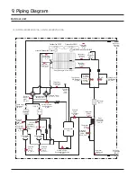
Страница 61: ...uidpipe T_L BallValve Liquidpipe BV_L Pressure Sensor Low PS_L CheckValve EEVBypass CV_EB SolenoidValve 4Way V_4W HeatExchanger Main HX_M Thermistor Discharge pipe T_D Thermistor Compressor Top T_CT Pressure Switch High PW_H SolenoidValve AccumulatoroilReturn V_AR Accumulator AC Pressure Sensor High PS_H Compressor1 COMP1 CheckValve Discharge CV_D Oil Separator OS Solenoid Valve EVIBypass V_EB The...

Страница 62: ...olenoidValve AccumulatoroilReturn V_AR Pressure Sensor Low PS_L SolenoidValve HotGasbypass V_HG Solenoid Valve EVI1 V_EVI1 Compressor1 COMP1 Thermistor Discharge1 pipe T_D1 Thermistor Compressor Top1 T_CT1 CheckValve Discharge1 CV_D1 Accumulator AC CheckValve EEVBypass CV_EB SolenoidValve 4Way V_4W Pressure Sensor High1 PS_H1 Solenoid Valve EVI2 V_EVI2 T_D2 T_CT2 CV_D2 Thermistor EVIOut T_EO Oil S...

Страница 63: ...ure Sensor Low PS_L SolenoidValve HotGasbypass V_HG Solenoid Valve EVI1 V_EVI1 Compressor1 COMP1 Thermistor Discharge1 pipe T_D1 Thermistor Compressor Top1 T_CT1 CheckValve Discharge1 CV_D1 Accumulator AC CheckValve EEVBypass2 CV_EB2 E_M1 SolenoidValve 4Way V_4W Pressure Sensor High1 PS_H1 Solenoid Valve EVI2 V_EVI2 T_D2 T_CT2 CV_D2 Thermistor EVIOut T_EO Oil Separator1 OS1 OS2 Pressure Switch Hig...

Страница 64: ...e Sensor Low PS_L SolenoidValve HotGasbypass V_HG Solenoid Valve EVI1 V_EVI1 Compressor1 COMP1 Thermistor Discharge1 pipe T_D1 Thermistor Compressor Top1 T_CT1 CheckValve Discharge1 CV_D1 Accumulator AC CheckValve EEVBypass2 CV_EB2 E_M1 SolenoidValve 4Way V_4W Pressure Sensor High1 PS_H1 Solenoid Valve EVI2 V_EVI2 T_D2 T_CT2 CV_D2 Thermistor EVIOut T_EO Oil Separator1 OS1 OS2 Reservoir RE Pressure...

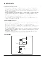
Страница 65: ... 1 Do not install the product in a place where it is directly exposed to sea water and sea breeze Make sure to install the product behind a structure such as building that can block see breeze Even when it is inevitable to install the product in seashore make sure that product is not directly exposed to sea breeze by installing a protection wall 2 Consider that the salinity particles clinging to t...

Страница 66: ... an area with weak electromagnetic waves and put the main power cable and communication cables in a separately installed protection tube Make sure that there is no equipment that generates electromagnetic waves If not electromagnetic waves may cause problem to the control systems which may lead to air conditioner malfunction Example Remote control sensor of the indoor unit may not receive the sign...

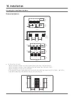
Страница 67: ...because the refrigerant running of MCU may create noise Outdoor unit space requirements Space requirement was decided based on following conditions Cooling mode outdoor temperature of 35 C 95 F Larger space is required if the outdoor temperature is higher than 35 C 95 F or if the place is heated easily by quantity of solar radiation When you secure installation space consider path for people and t...

Страница 68: ...in value h1 h2 additional clearance h1 2 h2 2 Half of the exceeded height should be added to the service space S1 S2 Unit mm inch Case 3 Over 500 20 Over 500 20 Over 600 24 Over100 4 Over100 4 Over100 4 Over100 4 Over100 4 Over100 4 Over100 4 Over100 4 Front side Front side Case 2 Over 200 8 Over 300 12 Over 400 16 Over 400 16 Height of the wall is unlimited Front side Case1 Over 100 4 Over 300 12...

Страница 69: ...el Name Specification MBH kW Y Joint Only H R MXJ YA1500M 76 and below 22 4 and below MXJ YA2500M ߩߩड़ߤߦߢ ߤߤ ߧ ड़ߩߢ ߥ MXJ YA3100M ߤߦߣड़ߦߨߣ ߩߢ ߦ ड़ߣߥߧ ߤ MXJ YA3800M Over 461 Over 135 2 Distribution header MXJ HA2512M 154 and below for 4 rooms 45 0 and below for 4 rooms MXJ HA3115M 240 and below for 8 rooms 70 3 and below for 8 rooms MXJ HA3819M ߤߦߣ ड़ ߦߨߣ for 8 rooms ߩߢ ߦ ड़ ߣߥߧ ߤ for 8 rooms Y Joint Out...

Страница 70: ...d the wind speed of 30m s If you cannot fix the outdoor unit on the base ground fix it by side or use extra structure 5 In heating operation defrost water may form so you must really care about the drainage and waterproofing the floor To prevent defrost water from stagnating or freezing construct a drainage with over 1 50 slope Ice may form on the floor in winter season 6 It is necessary to add wi...

Страница 71: ...ound Hbeamoranti vibration frame Over 200 8 Over 200 8 Over 50 2 A B C 54 2 13 730 28 75 765 30 12 54 2 13 Anti vibration Base ground ࣈߦࣛ ࣉ ߣߩ ߢ ߪߣף Unit mm inch Outdoorunit Anti vibration θɇ ʪ ࣈߦࢩߪࣛ ࣉ ߩߦ ߢ ߤߣף Unit mm inch Classification DVM S2 Small type DVM S2 Large type DVM S2 X Large type A 930 36 6 1295 51 1860 73 2 B 790 31 1 1155 45 5 1720 67 7 150 5 9 C Outdoorunitinstallation ...

Страница 72: ...utdoor unit is installed on the roof check the strength and waterproof status of the roof Unit mm inch 960 37 80 760 29 92 100 3 94 80 3 15 80 3 15 80 3 15 6 0 120 4 73 X X Direction of the drainage Slope1 50 Drainage work for single installation B A 50 1 97 100 3 94 150 5 91 100 3 94 X X SECTION 80 3 15 80 3 15 80 3 15 80 3 15 80 3 15 80 3 15 80 3 15 80 3 15 6 0 6 0 240 9 45 B B Direction of the ...

Страница 73: ...r unit on the rooftop check the strength and make sure to waterproof the rooftop Construct draining pit around the base construction and pay attention to the drainage around the outdoor unit Condensation or defrost water may form during outdoor unit operation If there s any possibility of small animals from entering the pipe outlet block the outlet as shown in the illustration Liquid side pipe Gas...

Страница 74: ...ign substance may enter into the product and there could be a risk of personal injury Wear protection equipment at all times when making galvanized sheet metal duct since the orker may get injured by the sharp parts When installing the outdoor unit under the tree or near forest leafs may get into the product and cause problems on the product Therefore install a discharge duct to prevent foreign su...

Страница 75: ...may accumulate if the area of the frame or the base ground is larger hh Installing the outdoor unit in windy region In windy regions such as near sea shores protection wall or wind protection duct must be installed for normal operation of the outdoor unit Refer to the illustration of the snow prevention duct for installing the wind protection duct Install the wind prevention duct with the consider...

Страница 76: ...53 45 39 DVM S2 Small type 558 21 97 1330 52 36 558 21 97 871 34 29 2413 95 345 13 58 723 28 46 723 28 46 723 28 46 464 18 27 180 7 09 980 38 58 668 26 3 532 20 94 567 22 32 765 30 12 540 21 26 180 7 09 953 37 52 1123 44 21 2271 89 41 1150 45 28 1632 64 25 2300 90 55 1285 50 59 1408 55 43 723 28 46 980 38 58 668 26 3 953 37 52 1123 44 21 2273 89 49 532 20 94 1634 64 33 2302 90 63 1150 45 28 180 7 ...

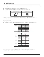
Страница 77: ...rant pipe and there shouldn t be any harmful ion oxide dust iron content or moisture inside pipe Use tools and accessories that fit on R 410A only Installation process Compatibilitywith Tool purpose conventional tool Pipe cutter Pipe cutting Compatible Flaring tool Pipe flaring Apply Exclusive etheroil ester oil alkali benzene oil or synthetic oil Refrigerant refrigerant machine oil Refrigerant oil...

Страница 78: ...rigerant pipe according to main pipe size of each outdoor unit capacity When the pipe length including elbow between an outdoor unit and the farthest indoor unit exceeds 90m 295ft you must increase the size of the pipe main pipe by one grade which connects between the outdoor unit to the first branch joint ...

Страница 79: ...ख़ AɇΧɇʀ ϩц ॗ ߧߢ ߦ MXJ YA2812M ߣߩߤ ख़ AɇΧɇʀ ϩц ॗ ߤߦߪ ߧߢ ߦ ख़ AɇΧɇʀ ϩц ॗ ߩߤ ߪ MXJ YA2815M ߤߦߪ ख़ AɇΧɇʀ ϩц ॗ ߥߦߦ ߩߤ ߪ ख़ AɇΧɇʀ ϩц ॗ ߣߢߢ ߪ MXJ YA3419M ߥߦߦ ख़ AɇΧɇʀ ϩц ॗ ߦߩߪ ߣߢߢ ߪ ख़ AɇΧɇʀ ϩц ॗ ߣߦߢ MXJ YA4119M 478 Capacity 140 Capacity MXJ YA4422M Distribution header E Capacity 172 for 4 rooms Capacity 50 4 for 4 rooms MXJ HA2512M Capacity 248 for 8 rooms Capacity 72 8 for 8 rooms MXJ HA3115M Capacity 478 fo...

Страница 80: ...θ ͱиɇɵ ʪ ʪ ϩ ʀ ϩ ʀ ϩ 6 Ɵ ϑ ʀɇΧɇʀ ϩц ϑ ͱϩ ϑЇΧΧͱθϩʪʒ 8 This capacity is not supported 10 9 52 3 8 50 164 12 7 1 2 200 656 12 9 52 3 8 30 98 12 7 1 2 160 525 14 12 7 1 2 90 295 15 88 5 8 200 656 16 12 7 1 2 90 295 15 88 5 8 200 656 18 12 7 1 2 80 262 15 88 5 8 200 656 20 12 7 1 2 60 197 15 88 5 8 190 623 22 15 88 5 8 90 295 19 05 3 4 200 656 24 15 88 5 8 90 295 19 05 3 4 200 656 26 15 88 5 8 90 295 1...

Страница 81: ... 1 4 10m 32 8 1 4 15m 49 2 3 8 10m 32 8 3 8 10m 32 8 3 8 10m 32 8 3 8 10m 32 8 1 4 5m 16 4 3 8 10m 32 8 144MBH 12Ton 12MBH 24MBH 24MBH 18MBH 18MBH 18MBH 18MBH 12MBH Classification AM072BXVG AM096BXVG AM120BXVG AM144BXVG Basic amount lb kg 13 7 6 2 17 6 8 17 6 8 23 1 10 5 Classification AM168BXVG AM192BXVG AM216BXVG AM240BXVG Basic amount lb kg 23 1 10 5 27 6 12 5 34 2 15 5 34 2 15 5 Size of liquid...

Страница 82: ...nding AM NFDCH AM NGDCH 0 26 0 12 0 49 0 22 0 49 0 22 0 71 0 32 0 71 0 32 Ceiling AM NCDCH 0 86 0 39 0 86 0 39 1 23 0 56 2 09 0 95 MPAHU V AHU AM NZDCH 0 73 0 33 1 10 0 50 1 10 0 50 1 83 0 83 1 94 0 88 2 60 1 18 2 80 1 27 3 73 1 69 3 73 1 69 Wallmounted withEEV AM NVDCH AM NQDCH 0 51 0 23 0 51 0 23 0 71 0 32 0 71 0 32 1 06 0 48 1 06 0 48 1 06 0 48 1 41 0 64 1 50 0 68 MCU MCU S NE N 1 10 0 50 If AH...

Страница 83: ...d pipe Ø6 35 Ø1 4 35 114 8 0 02 0 013 0 7 1 49 5 575 12 19 Ø9 52 Ø3 8 50 164 0 0 06 0 040 3 0 6 56 Ø12 70 Ø1 2 15 49 2 0 125 0 084 1 875 4 13 Classification Model name of indoorunit Numberofindoorunits Unitamountofrefrigerant kg EA lb EA Amount of additional refrigerant kg lb Total amount of additional refrigerant kg lb Indoorunit 4waycassette AM018RN4DCH 4 0 57 1 26 2 28 4 92 3 78 8 22 LSPduct AM...

Страница 84: ...ure to prevent any damages on the exterior of the outdoor unit Remove all burrs around the knock out hole and apply varnish on the cross section and edges of the knock out hole to prevent rust Use a cable protection tube and bushing to prevent a cable from being damaged when passing through a knock out hole Pipe installation for an outdoor unit 1 Direction of the pipe Refrigerant pipe can be withd...

Страница 85: ...g the sealed pipe on the bottom side of the service valve cut it with a pipe cutter first and then start the welding When the sealed pipe is welded without cutting you may get injured by the refrigerant within the pipe Classification Front side connection Right left and bottom side connection Working process First remove the piping coverfrom the outdoorunit Separate the knock out hole that you are ...

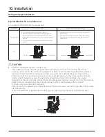
Страница 86: ...r units Check the changes in comparison with the DVM Ⅱ Ⅲ and Ⅳ Caution Correct installation Incorrect installation Refrigerant pipes should be connected at the same orlower level than the ones connected to the outdoorunit Refrigerant pipes must be connected by the side of the product Straight section should be 300mm 12inch or more Branch joint between outdoor units must be installed horizontally I...

Страница 87: ...Refrigerantpipeinstallation 10 Installation Examples of refrigerant pipe installation 1 Using Y joint 2 Usingdistribution header ...

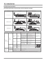
Страница 88: ...le length of pipe Outdoor Ї ϩ ड़ Indoorunit Actual length Equivalent length 200 m 656 and below 220 m 722 and below Installing only with Y joint ɇॐɵॐʀॐʒॐʪॐ ॐ ॐΧ ख़ 200 m 220 m 656 722 Equivalent length Y joint 0 5 m 1 64 Distribution header 1 m 3 28 Installing with Y joint and distribution header ɇॐɵॐ ख़ ߤߢߢ ߤߤߢ ࡥ ɇॐ ॐ ख़ 200 m 220 m 656 722 Installing only with distribution header ɇॐ ख़ ߤߢߢ ߤߤߢ ࢩߨߧߨ ߩ...

Страница 89: ...quired conditions must be satisfied EEV kit Model name Remarks kkǤ ϩ ड़ Ã ʒͱͱθ Ї ϩ Actual pipe length 2m 6 6 MEV E24SA 1 indoor Apply to products without EEV Wall mount ceiling MEV E32SA 20m 66 or less MXD E24K132A 2 indoor MXD E24K200A MXD E32K200A MXD E24K232A 3 indoor MXD E24K300A MXD E32K224A MXD E32K300A Classification Condition Example θϑϩ ɵθɇ ʀ ͱ ϩ ड़ FarthestIndoorunit ߦߧ ߣߦߪࣱ ख़ ɵॐʀॐʒॐʪॐ ॐ ॐ...

Страница 90: ...pe connection welding Liquid pipe connection welding 70 mm When installing MCU use the pattern sheet for installation that is provided with the product When welding the gas pipes protect the product with the flame proof sheet When connecting the MCU with outdoor units default direction is set in the MCU If installing opposite direction weld the enclosed copper cap in each high pressure low pressur...

Страница 91: ...0 70 0 34Ton AM408BXVGF 60 ߤߢߪड़ߤߥߢ 22 5 22 5 4 6 4 6 60 0 70 0 24 3 24 3 4 6 4 6 64 0 80 0 36Ton AM432BXVGF 60 ߤߢߪड़ߤߥߢ 24 3 24 3 4 6 4 6 64 0 80 0 24 3 24 3 4 6 4 6 64 0 80 0 38Ton AM456BXVGF 60 ߤߢߪड़ߤߥߢ 14 4 14 4 4 2 4 2 40 8 45 0 19 6 19 6 4 2 4 2 52 6 60 0 22 5 22 5 4 6 4 6 60 0 70 0 40Ton AM480BXVGF 60 ߤߢߪड़ߤߥߢ 14 4 14 4 4 2 4 2 40 8 45 0 20 4 20 4 4 2 4 2 54 4 60 0 22 5 22 5 4 6 4 6 60 0 70 0 N...

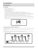
Страница 92: ...er o not use the ower cable with the core wire e osed due to insulator damage occurred during remo al of the sheath hen the core wire is e osed it ma cause fire Insulator innercover Exposedwire core The example of exposed corewire Sheath outercover Power and communication cable configuration Main power and the ground cable must be withdrawn through the knock out hole on the bottom right or right s...

Страница 93: ...n the illustration Name Tempergrade Applicable conditions When the protection tube is installed indoorand not exposed to outside because it is embedded in concrete structure Flexible PVC conduit PVC When the protection tube is installed indoor but exposed to outside so there are risk of damage to the protection tube Class 1 flexible Galvanized conduit steel sheet When the protection tube is install...

Страница 94: ...or or Communication cable ĮЇϩʒͱͱθ Ї ϩ ड़ Ã ʒͱͱθ unit Communication cable ĮЇϩʒͱͱθ Ї ϩ ड़ ĮЇϩʒͱͱθ unit Connect a power cable of the outdoor unit after checking that R S T 3 phase 3 wire is properly connected Malfunction may occur if one or more of the wires among R S T phases 3 Phases 3 Wires are not connected properly Malfunction Turing on off occurrence of error consecutive reset Communication cable...

Страница 95: ... 2 17 5 1 2 Allowance mm inch 0 3 0 011 0 2 0 007 0 3 0 011 0 2 0 007 0 3 0 011 0 2 0 007 0 5 0 019 0 2 0 007 0 5 0 019 0 2 0 007 0 5 0 019 0 2 0 007 0 5 0 019 0 4 0 015 d1 Standard dimension mm inch 3 4 1 8 4 5 3 16 5 8 1 4 7 7 5 16 9 4 3 8 11 4 7 16 13 3 1 2 Allowance mm inch 0 2 0 007 0 2 0 007 0 2 0 007 0 2 0 007 0 2 0 007 0 3 0 011 0 4 0 015 E Min mm inch 6 1 4 7 9 5 16 9 5 5 16 11 3 8 12 5 1...

Страница 96: ...e power cablewith a cable tie Solderless ring terminal Cable tie 1 Front connection 10 Installation Connecting the power terminal 2 Closing the cover CAUTION When removing the outer sheath of the power supply cable be careful not to scratch the inner sheath of the cable Make sure that more than 20mm 0 79inch of the outer sheath of the indoor unit power and communication cable are inside the electr...

Страница 97: ...the vibration of the compressor is transferred to the pipes and can damage the power supply cables or pipes creating the danger of fire or explosion Make sure that the place where the sheath of power supply cable is removed is inside the power supply box If it is impossible you should connect the protection tube for power cable to the power supply box After arranging the power cable into the power...

Страница 98: ...ration fix it with cable tie 3 Fix the housing which has an insulator to the terminal board Fixing the ground cable Grounding Connect the ground cable to the grounding hole inside the power supply box Withdrawing the power cable Withdrawing from the front side Connect the power cable protection tube into the power supply box as shown picture Be sure that the power supply cable is not damaged by bu...

Страница 99: ...F2 OF1 OF2 R1 R2 Terminal block with indoorunit Terminal block with outdoor unit sub module Terminal block with solution device A Where to install the interface module Install the interface module in location A considering the installation conditions For details on how to install refer to the interface module installation manual ...

Страница 100: ...0 24 80 23 70 3 53 3 45 2 31 2 60 26 40 23 90 AM240BXVG 228 000 258 000 10 60 10 60 22 60 23 30 3 35 3 25 2 12 2 45 26 40 23 70 AM264BXVG 252 000 282 000 11 80 11 50 26 30 21 50 3 61 3 55 2 52 2 40 25 70 24 80 AM288BXVG 274 000 308 000 11 90 11 40 25 90 22 50 3 60 3 50 2 50 2 40 24 50 23 70 AM312BXVG 298 000 334 000 11 10 11 10 24 30 21 70 3 60 3 45 2 50 2 35 24 40 21 20 AM336BXVG 320 000 360 000 ...

Страница 101: ...Head Office Suwon Korea 129 Samsung Ro Yeongtong Gu Suwon City Gyeonggi Do Korea 16677 Website www samsung com https partnerhub samsung com E mail airconditioner samsung com Images and data in this book may subject to change without prior notice ...

Отзывы: