14
2
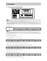
NOTE
Before a test run, check whether the power wire is disconnected or misconnected.
If the power wire is disconnected or misconnected, error code displays or power is not supplied or major part is not operated.
The pump built-in model is able not to operate or to be occurred trip of OCR or to reverse rotation of pump, especially if the power wire
is disconnected or misconnected.
1. Turn on th
e
pro
d
u
c
t.
2
. Ch
ec
k i
f
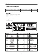
DIP
S
/W 1 is on.
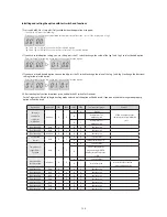
DIP S/W
No.1
On
Off
Main control
Remote control
NOTE
When set as main control, the product do not receive any control of external contact, module control, and upper controller, and any
orders from module/group control.
3
. W
a
t
e
r si
de
pr
e
ssur
e
s
e
nsor
ca
li
b
r
a
tion
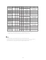
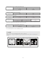
- Sensor calibration operates for more precise water rate inspection.
- It operates in main control only.
- Water flow in the system must not exist when calibrating sensor.
- Press and hold K4 and K6 for 3 seconds to start the calibration when operation of the product and the pump is off.
Seg1
Seg2
Seg3
Seg4
Seg5
Seg6
K
C
A
L
I
- The operation will finish automatically within 30 seconds.
- The product and the pump cannot be operated while calibrating the pressure difference.
4. For
ced
fa
n
f
un
c
tion r
e
mov
e
s
acc
umul
a
t
ed
snow on th
e
fa
n.
S
kip this st
e
p i
f
snow is not
acc
umul
a
t
ed
.
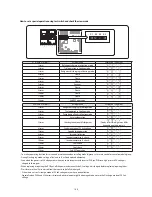
- Press and hold K6 for 3 seconds when operation is off and the fan will operate.
Seg1
Seg2
Seg3
Seg4
Seg5
Seg6
K
F
A
N
- During forced fan function, press K6 and the operation will stop.
- If the operation is on during forced fan function, the fan will stop.
5. For
ced
pump
f
un
c
tion
c
h
ec
ks i
f
w
a
t
e
r
f
low is norm
a
l.
- Press and hold K5 for 3 seconds when operation is off and the pump will operate.
Seg1
Seg2
Seg3
Seg4
Seg5
Seg6
K
P
U
M
P
- During forced pump function, press K5 and the operation will stop.
- If the operation is on during forced pump function, the pump will stop.
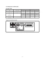
HYDRO-UNIT_MODULE_CHILLER
K1
K2
K3
K4
K5
K6
K1
K2
K3
K4
K5
K6
88-SEG DISPLAY
TACT S/W
DIP S/W
9. Trial Operation
9-1. Trial operation for each CHILLER unit
Содержание AG042KSVANH
Страница 102: ...98 1 2 3 4 5 6 8 9 10 11 13 12 14 7 ASSY PCB MAIN HYDRO cont Model All models name is commonness ...
Страница 104: ...100 3 2 1 5 4 6 7 8 9 10 11 12 13 14 15 16 5 2 ASSY PCB MAIN Model All models name is commonness ...
Страница 106: ...102 1 2 3 4 5 6 7 8 9 10 11 12 13 14 15 5 3 ASSY PCB SUB FAN Model All models name is commonness ...
Страница 109: ...105 1 2 4 3 5 6 7 8 9 10 11 5 5 ASSY PCB SUB EMI PF 9 H power model only cont Model AG070KSV666 Series ...
Страница 111: ...107 5 6 ASSY PCB MAIN HUB Model All models name is commonness DC 1 2 3 4 5 6 7 8 9 10 11 12 ...
Страница 113: ...109 ASSY PCB MAIN HUB cont Model All models name is commonness AC 1 1 2 3 4 5 6 7 8 9 10 11 ...
Страница 115: ...111 5 7 ASSY PCB INVERTER PF 8 Model AG042 056KSV666 Series 4 2 3 5 1 8 9 7 6 ...
Страница 117: ...113 ASSY PCB INVERTER PF 9 cont Model AG070KSV666 Series 10 8 4 9 7 6 11 12 13 1 2 3 5 ...

