


9
English
Ins
tallation Pr
oc
edur
e
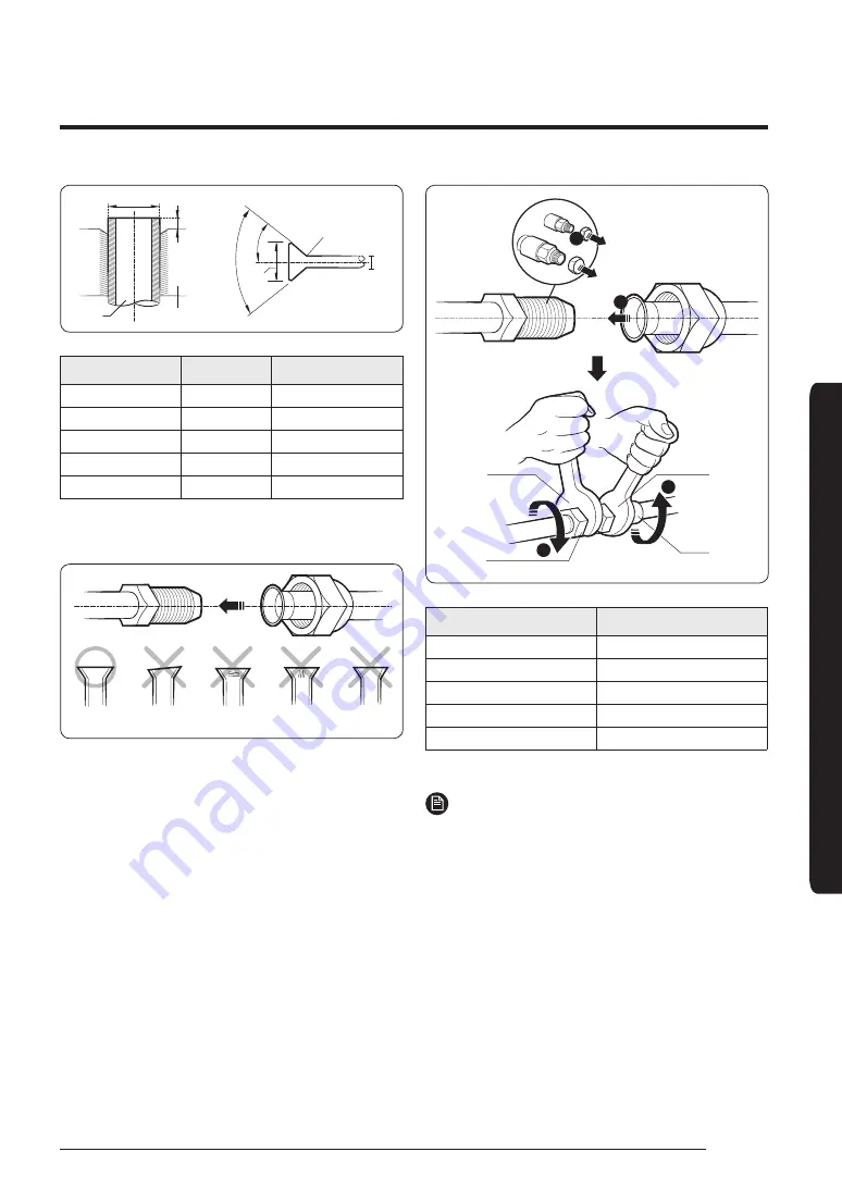
Pipe
Flare
D
A
Flare
90° ±2°
R 0.4 to 0.8 mm
D
L
45
°
±2
°
Outer Diameter (D)
Depth (A)
Flare dimension (L)
Ø6.35 mm
1.3 mm
8.7 to 9.1 mm
Ø9.52 mm
1.8 mm
12.8 to 13.2 mm
Ø12.70 mm
2.0 mm
16.2 to 16.6 mm
Ø15.88 mm
2.2 mm
19.3 to 19.7 mm
Ø19.05 mm
2.2 mm
23.6 to 24.0 mm
5
Check that the flaring is correct, referring to the
illustrations below for examples of incorrect flaring.
Correct
Inclined
Damaged
Surface
Cracked
Uneven
Thickness
Step 6 Connecting the assembly
pipes to the refrigerant pipes
There are two refrigerant pipes of different diameters :
• A smaller one for the liquid refrigerant.
• A larger one for the gas refrigerant. The inside of copper
pipe must be clean and has no dust.
1
Remove the pinch pipe on the pipes and connect the
assembly pipes to each pipe, tightening the nuts, first
manually and then with a torque wrench, a spanner
applying the following torque.
2
3
3
1
Torque
wrench
Flare nut
Spanner
Union
Outer diameter (mm)
Torque (N•m)
Ø6.35
14 to18
Ø9.52
34 to 42
Ø12.70
49 to 61
Ø15.88
68 to 82
Ø19.05
100 to 120
(1 N•m=10 kgf•cm)
NOTE
• If the pipes must be shortened, see
Step 5 Cutting and
flaring the pipes
on page
8
.
2
Be sure to use an insulator thick enough to cover the
refrigerant tube to protect the condensate water on the
outside of the pipe falling onto the floor and to improve
the efficiency of the unit.
3
Cut off any excess foam insulation.
4
Make sure that there are no cracks or waves on the bent
area.
5
It would be necessary to double the insulation thickness
(10 mm or more) to prevent condensation even on the
insulator when if the installed area is warm and humid.
Содержание AC TNCDKC Series
Страница 26: ......


