background image

1

Operation

The application software is ready for operation with the default temperature and time schedule
settings after it has been transferred to the TROVIS 5571 PLC.
On start-up,

the language as well as the current time and date

must be set in the controller. Re-

fer to section 1.6.

1.1

Operating elements

1.1.1 Operating keys

The keys are located in the front panel of the PLC and protected by a Plexiglas door.

Changeover key

(press with pen or other pointed item

)

Switch between the operating level and settings level

Reset key

(press with pen or other pointed item)
Resets the PLC.

NOTICE

The application in the controller is deleted.

Cursor key(s)

– Navigate within levels
– Change values

Enter key

– Open levels
– Activate editing mode for parameters and function blocks
– Confirm entered settings

EB 5571-2 EN

5

Operation

Содержание TROVIS 5500

Страница 1: ...utomation System TROVIS 5571 Programmable Logic Controller PLC Standard Application for Lag Lead Sequence WT71 Operating Instructions EB 5571 2 EN Electronics from SAMSON Firmware version 1 50 Edition...

Страница 2: ...tain important information on the installation electrical connection start up and communication of the TROVIS 5571 Programmable Logic Controller 4 The device may only be assembled started up or opera...

Страница 3: ...eat exchanger 22 4 1 Parallel operation 22 4 2 Lag lead sequence control 22 4 2 1 Unrestricted sequence 23 4 2 2 Outdoor temperature dependent sequence 23 4 2 3 Sequence lock over the binary input 24...

Страница 4: ...tation 37 7 6 Condensate accumulation control 38 7 7 Three step control 39 7 8 Continuous control 40 7 9 Processing an external demand 42 7 10 Separate set point 43 7 11 Position feedback 43 7 12 Forw...

Страница 5: ...1 1 1 Operating keys The keys are located in the front panel of the PLC and protected by a Plexiglas door Changeover key press with pen or other pointed item Switch between the operating level and se...

Страница 6: ...ight mode Standby mode The heat exchanger only works when there is a demand for domestic hot water or a demand for an external set point The protective functions remain active Night mode reduced mode...

Страница 7: ...lect operating mode Confirm selected operating mode Exit setup menu Select Zur ck Back Exit overview menu Display Start screen EB 5571 2 EN 7 Operation bersicht Anl x x Betriebsart Tag Freigabe 1 F hr...

Страница 8: ...r Display bersicht Overview Select Service Open the service menu Display Service The Language menu item is highlighted Select Language menu item Select language Confirm language selected After selecti...

Страница 9: ...t exchanger 2 and 3 running heat exchanger 1 switched off Lead heat exchanger based on selection 4 1 2 3 Heat exchanger 1 2 and 3 running Lead heat exchanger based on selection If more than one heat e...

Страница 10: ...m Activate the controller editing mode for F hrungstau scher lead heat exchanger Display F hrungstauscher lead heat exchanger blinks Set lead heat exchanger Confirm setting Exit overview Select Zur ck...

Страница 11: ...system time set in the PLC 4 Automatic summer time The summer time is automatically set on the last Sunday in March at 02 00 h and the winter time on the last Sunday in October at 03 00 h The control...

Страница 12: ...change the current setting on off of the Automatic summer time function Activate function Automatic summer time Ein On Deactivate function Automatic summer time Aus Off Exit the Datum Uhrzeit Date Tim...

Страница 13: ...em Anl x 0 If a consumer on the secondary side exists the setting is performed in the menu bersicht Pa rameter Heizkreis 1 3 The time schedules of DHW heating is programmed separately for the DHW and...

Страница 14: ...e steps of 30 minutes Confirm stop time Display Start time of the second time schedule blinks The second time schedule is set like the first time schedule To set the time schedules for each day repeat...

Страница 15: ...Feiertage Public holidays menu item Display Feiertage Public holidays Activate the editing mode for public holidays Display 0 first figure for day of month blinks Select date Confirm date Display 01 f...

Страница 16: ...ameters as the parameters of the application are reset to the default settings on changing the system code number Before setting the parameters in the service menu the application key number must be e...

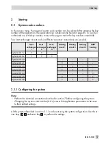
Страница 17: ...at exchanger 3 Heating circuit 1 Heating circuit 2 Heating circuit 3 DHW heating System Anl 1 x System Anl 2 x System Anl x 0 System Anl x 1 System Anl x 2 System Anl x 3 System Anl x 4 System Anl x 5...

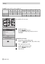
Страница 18: ...triebsart Operating mode menu item is highlighted Opening the service menu Activate the controller editing mode Display Schl sselzahleingabe Key number entry 0000 blinks Enter application key number C...

Страница 19: ...diting mode for Anlage konfigurieren Configure system The system configuration starts with system Anl 1 0 two heat exchangers Select third heat exchanger Confirm selection Select heating circuit 1 Sel...

Страница 20: ...t exchangers is to be chan ged proceed as follows Select required heat exchanger W rmetauscher 1 3 Activate the editing mode for W rmetauscher x Display W rmetauscher x Heat exchanger x The menu item...

Страница 21: ...nd a shut off valve Kl are in cluded in the control Heat exchangers that are not in operation are shut off hydraulically by the shut off valve Kl1 Kl2 or Kl3 As soon as a heat exchanger starts running...

Страница 22: ...nable lag lead sequence 2 bersicht Parameter Allgemein Folgebetrieb Parameters WE Adjustment range Folge sequence parallel Depending on outdoor temp Outdoor temperature dependent unrestricted parallel...

Страница 23: ...energy required to heat the flow temperature The lag heat exchanger first stops running when the total of the modulation of all the heat exchangers is smaller than the OFF switching point parameter 2...

Страница 24: ...emperature is de termined by the binary input The outdoor sensor is not required 2 bersicht Parameter Allgemein Folgebetrieb Parameter WE Adjustment range Folge sequence Au entemp abh ngig outdoor tem...

Страница 25: ...es are above this limit the smaller heat exchanger leads Whereas when the outdoor temperatures are below the limit the larger heat exchanger leads To prevent a lag lead sequence change when the outdoo...

Страница 26: ...e can take place Parameter WE Adjustment range F hrungswechsel sequence change Betreib Std operating hours AUS Outdoor temp rating operating hours OFF Folgeumkehr Intervall time interval for lag lead...

Страница 27: ...Note The programming of times of use and public holidays are described in detail in section 1 7 Systems without consumers on the secondary side 2 bersicht Parameter Allgemein Zeitprogramme Systems wi...

Страница 28: ...ture is controlled according to the outdoor temperature The heating characteristic in the controller defines the flow temperature set point as a function of the outdoor temperature Fig 1 28 EB 5571 2...

Страница 29: ...mperature Examples for adjusting the characteristic 4 Old building radiator design 90 70 Gradient approx 1 8 4 New building radiator design 70 55 Gradient approx 1 4 4 New building radiator design 55...

Страница 30: ...e selected after the application key number has been entered Parameter WE Adjustment range Kennlinienart type of character istic 4 Punkte four point Steigung Four point gradient fixed set point 2 bers...

Страница 31: ...C 20 to 160 C Vorlauftemp max max flow temperature 90 C 20 to 120 C Vorlauftemp min min flow temperature 20 C 20 to 120 C 5 1 3 Fixed set point control The flow temperature can be regulated to a fixed...

Страница 32: ...n Systems with consumers on the secondary side 2 bersicht Parameter Heizkreis 1 3 Parameters WE Adjustment range Vorlauftemp Sollwert flow temperature set point 70 C 20 to 160 C Absenkdifferenz set ba...

Страница 33: ...nt defines the set point at the flow sensor VFg Operation with storage tank thermostat BE3 to ModBus I O 1402 0328 3 The storage tank thermostat is connected at SF1 and switches the storage tank charg...

Страница 34: ...flow tempe rature limitation suspended 4 excessively high storage temperatures after thermal disinfection has been concluded 4 lime scale possibly which can have a negative effect on heat exchanger pe...

Страница 35: ...of use can be entered individually for each day of the week or together for all days of the week Monday to Sunday Note The programming of times of use and public holidays are described in detail in s...

Страница 36: ...tdoor temperature dependent deactivation works separately from the summer mode function 7 2 Summer mode Summer mode is activated depending on the mean daytime temperature measured between 7 00h and 22...

Страница 37: ...oes not replace the function of a safety temperature limiter 7 5 Return flow temperature limitation The return flow temperature limitation is performed separately for each heat exchanger If the temper...

Страница 38: ...he controller for R F3 heat exchanger WT3 Note To be able to keep to the defined return flow temperature limit make sure that the hea ting characteristic is not selected too steep and the speed of the...

Страница 39: ...valve to travel through the range of 0 to 100 Heat exchanger control circuit Rk1 to Rk3 The control valves are connected to the binary outputs listed below 4 BA3 and BA4 of the controller for heat exc...

Страница 40: ...portional component immediately causes the 0 to 10 V signal to change the greater KP the greater the change The integral components becomes effective with time TN represents the time which elapses unt...

Страница 41: ...r heating circuit HK1 4 AA6 at ModBus I O 1402 0328 2 for heating circuit HK2 4 AA6 at ModBus I O 1402 0328 3 for heating circuit HK3 Note Alternative assignment is shown in section 8 1 2 bersicht Ser...

Страница 42: ...to 10 V correspond to the range External demand 0V to External demand 10V 2 bersicht Parameter Allgemein Parameter WE Adjustment range Externer Bedarf 0V external demand 0 C 0 to 150 C Externer Bedarf...

Страница 43: ...is issued as a signal 4 Position feedback SRM1 at UE5 heat exchanger WT1 0 to 10 V or 1 to 2 k 4 Position feedback SRM2 at UE4 heat exchanger WT2 0 to 10 V or 1 to 2 k 4 Position feedback SRM3 at Mod...

Страница 44: ...ontroller over Modbus 2 bersicht Parameter Allgemein Parameter WE Adjustment range Au entemp senden St Nr send outdoor temp to st no AUS AUS off 5 to 255 Note This function is available in firmware ve...

Страница 45: ...e tank charging pump AF Outdoor sensor R F1 3 Heat exchanger return flow sensor R F4 6 Heating circuit return flow sensor SF Storage tank sensor VF1 3 Heat exchanger flow sensor VF4 6 Heating circuit...

Страница 46: ...2 11 10 9 8 7 6 5 4 2 3 1 GND AA_GND RK1 RK2 Frg_WT1 Frg_WT2 SM_WT1 SM_WT2 SM_Pu1 SRM1 SM_Pu2 AF R F1 R F2 VF1 VF2 SRM2 VFg WWA ext Bdf L1 N MODBUS RS 232 _ _ RK2 Pu1 Pu2 L1 L1 L1 N BA9 BA8 BA7 BA6 BA...

Страница 47: ...SRM1 SM_Pu2 AF R F1 R F2 VF1 VF2 SRM2 VFg WWA ext Bdf L1 N MODBUS RS 232 _ _ RK2 Pu1 Pu2 L1 L1 L1 N BA9 BA8 BA7 BA6 BA4 BA10 BA12 BA11 BA5 BA3 50 49 48 31 32 33 34 35 36 37 38 39 40 41 42 43 44 45 46...

Страница 48: ...SRM1 SM_Pu2 AF R F1 R F2 VF1 VF2 SRM2 VFg WWA ext Bdf L1 N MODBUS RS 232 _ _ RK2 Pu1 Pu2 L1 L1 L1 N BA9 BA8 BA7 BA6 BA4 BA10 BA12 BA11 BA5 BA3 50 49 48 31 32 33 34 35 36 37 38 39 40 41 42 43 44 45 46...

Страница 49: ...EB 5571 2 EN 49 RK5 HK2 GND AA6 BE5 BE4 BE3 BE2 BE1 21 20 19 18 17 16 15 14 13 12 11 10 9 8 7 R F5 VF5 GND HK2 _ Pu5 HK2 L1 L1 BA3 BA4 BA1 BA2 3 2 1 6 5 4 8 7 1402 0328 2 L1 N 230 V AC N N...

Страница 50: ...SRM1 SM_Pu2 AF R F1 R F2 VF1 VF2 SRM2 VFg WWA ext Bdf L1 N MODBUS RS 232 _ _ RK2 Pu1 Pu2 L1 L1 L1 N BA9 BA8 BA7 BA6 BA4 BA10 BA12 BA11 BA5 BA3 50 49 48 31 32 33 34 35 36 37 38 39 40 41 42 43 44 45 46...

Страница 51: ...7 16 15 14 13 12 11 10 9 R F6 VF6 GND HK3 _ Pu6 HK3 L1 L1 BA3 BA4 BA1 BA2 3 2 1 6 5 4 AA6 BE5 BE4 BE3 BE2 BE1 21 20 19 18 17 16 15 14 13 12 11 10 9 R F5 VF5 GND HK2 _ Pu5 HK2 L1 L1 BA3 BA4 BA1 BA2 3 2...

Страница 52: ..._WT2 SM_Pu1 SRM1 SM_Pu2 AF R F1 R F2 VF1 VF2 SRM2 VFg WWA ext Bdf L1 N MODBUS RS 232 _ _ RK2 Pu1 Pu2 L1 L1 L1 N BA9 BA8 BA7 BA6 BA4 BA10 BA12 BA11 BA5 BA3 50 49 48 31 32 33 34 35 36 37 38 39 40 41 42...

Страница 53: ...SM_Pu2 AF R F1 R F2 VF1 VF2 SRM2 VFg WWA ext Bdf L1 N MODBUS RS 232 _ _ RK2 Pu1 Pu2 L1 L1 L1 N BA9 BA8 BA7 BA6 BA4 BA10 BA12 BA11 BA5 BA3 50 49 48 31 32 33 34 35 36 37 38 39 40 41 42 43 44 45 46 47 R...

Страница 54: ...SM_Pu2 AF R F1 R F2 VF1 VF2 SRM2 VFg WWA ext Bdf L1 N MODBUS RS 232 _ _ RK2 Pu1 Pu2 L1 L1 L1 N BA9 BA8 BA7 BA6 BA4 BA10 BA12 BA11 BA5 BA3 50 49 48 31 32 33 34 35 36 37 38 39 40 41 42 43 44 45 46 47 R...

Страница 55: ...EB 5571 2 EN 55 RK5 HK2 GND AA6 BE5 BE4 BE3 BE2 BE1 21 20 19 18 17 16 15 14 13 12 11 10 9 R F5 VF5 GND HK2 _ Pu5 HK2 L1 L1 BA3 BA4 BA1 BA2 3 2 1 6 5 4 8 7 1402 0328 2 L1 N 230 V AC N N...

Страница 56: ...WT2 SM_Pu1 SRM1 SM_Pu2 AF R F1 R F2 VF1 VF2 SRM2 VFg WWA ext Bdf L1 N MODBUS RS 232 _ _ RK2 Pu1 Pu2 L1 L1 L1 N BA9 BA8 BA7 BA6 BA4 BA10 BA12 BA11 BA5 BA3 50 49 48 31 32 33 34 35 36 37 38 39 40 41 42 4...

Страница 57: ...EB 5571 2 EN 57 AA6 BE5 BE4 BE3 BE2 BE1 21 20 19 18 17 16 15 14 13 12 11 10 9 SRM3 GND RK3 _ Kl3 L1 L1 BA3 BA4 BA1 BA2 3 2 1 6 5 4 SM_WT3 SM_Pu3 GND GND Frg_WT3 _ 8 7 1402 0328 4 L1 N 230 V AC N N...

Страница 58: ...SRM1 SM_Pu2 AF R F1 R F2 VF1 VF2 SRM2 VFg WWA ext Bdf L1 N MODBUS RS 232 _ _ RK2 Pu1 Pu2 L1 L1 L1 N BA9 BA8 BA7 BA6 BA4 BA10 BA12 BA11 BA5 BA3 50 49 48 31 32 33 34 35 36 37 38 39 40 41 42 43 44 45 46...

Страница 59: ...EB 5571 2 EN 59 AA6 BE5 BE4 BE3 BE2 BE1 21 20 19 18 17 16 15 14 13 12 11 10 9 SRM3 GND RK3 _ Kl3 L1 L1 BA3 BA4 BA1 BA2 3 2 1 6 5 4 SM_WT3 SM_Pu3 GND GND Frg_WT3 _ 8 7 1402 0328 4 L1 N 230 V AC N N...

Страница 60: ...SRM1 SM_Pu2 AF R F1 R F2 VF1 VF2 SRM2 VFg WWA ext Bdf L1 N MODBUS RS 232 _ _ RK2 Pu1 Pu2 L1 L1 L1 N BA9 BA8 BA7 BA6 BA4 BA10 BA12 BA11 BA5 BA3 50 49 48 31 32 33 34 35 36 37 38 39 40 41 42 43 44 45 46...

Страница 61: ...1 10 9 SRM3 GND RK3 _ Kl3 L1 L1 BA3 BA4 BA1 BA2 3 2 1 6 5 4 AA6 BE5 BE4 BE3 BE2 BE1 21 20 19 18 17 16 15 14 13 12 11 10 9 R F5 VF5 GND HK2 _ Pu5 HK2 L1 L1 BA3 BA4 BA1 BA2 3 2 1 6 5 4 SM_WT3 SM_Pu3 GND...

Страница 62: ...SRM1 SM_Pu2 AF R F1 R F2 VF1 VF2 SRM2 VFg WWA ext Bdf L1 N MODBUS RS 232 _ _ RK2 Pu1 Pu2 L1 L1 L1 N BA9 BA8 BA7 BA6 BA4 BA10 BA12 BA11 BA5 BA3 50 49 48 31 32 33 34 35 36 37 38 39 40 41 42 43 44 45 46...

Страница 63: ...BE3 BE2 BE1 21 20 19 18 17 16 15 14 13 12 11 10 9 R F6 VF6 GND HK3 _ Pu6 HK3 L1 L1 BA3 BA4 BA1 BA2 3 2 1 6 5 4 AA6 BE5 BE4 BE3 BE2 BE1 21 20 19 18 17 16 15 14 13 12 11 10 9 R F5 VF5 GND HK2 _ Pu5 HK2...

Страница 64: ...9 8 7 6 5 4 2 3 1 GND AA_GND RK1 RK2 Frg_WT1 Frg_WT2 SM_WT1 SM_WT2 SM_Pu1 SRM1 SM_Pu2 AF R F1 R F2 VF1 VF2 SRM2 VFg WWA ext Bdf L1 N MODBUS RS 232 _ _ RK2 Pu1 Pu2 L1 L1 L1 N BA9 BA8 BA7 BA6 BA4 BA10...

Страница 65: ...10 9 SRM3 GND RK3 _ Kl3 L1 L1 BA3 BA4 BA1 BA2 3 2 1 6 5 4 AA6 BE5 BE4 BE3 BE2 BE1 21 20 19 18 17 16 15 14 13 12 11 10 9 SF2 SF1 GND Pu3 L1 BA3 BA4 BA1 BA2 3 2 1 6 5 4 SM_WT3 SM_Pu3 GND GND Frg_WT3 _...

Страница 66: ...2 SM_Pu1 SRM1 SM_Pu2 AF R F1 R F2 VF1 VF2 SRM2 VFg WWA ext Bdf L1 N MODBUS RS 232 _ _ RK2 Pu1 Pu2 L1 L1 L1 N BA9 BA8 BA7 BA6 BA4 BA10 BA12 BA11 BA5 BA3 50 49 48 31 32 33 34 35 36 37 38 39 40 41 42 43...

Страница 67: ...9 SRM3 GND RK3 _ Kl3 L1 L1 BA3 BA4 BA1 BA2 3 2 1 6 5 4 AA6 BE5 BE4 BE3 BE2 BE1 21 20 19 18 17 16 15 14 13 12 11 10 9 SF2 SF1 GND HK3 _ Pu6 HK3 L1 L1 BA3 BA4 BA1 BA2 3 2 1 6 5 4 SM_WT3 SM_Pu3 GND GND F...

Страница 68: ...2 SM_Pu1 SRM1 SM_Pu2 AF R F1 R F2 VF1 VF2 SRM2 VFg WWA ext Bdf L1 N MODBUS RS 232 _ _ RK2 Pu1 Pu2 L1 L1 L1 N BA9 BA8 BA7 BA6 BA4 BA10 BA12 BA11 BA5 BA3 50 49 48 31 32 33 34 35 36 37 38 39 40 41 42 43...

Страница 69: ...BE4 BE3 BE2 BE1 21 20 19 18 17 16 15 14 13 12 11 10 9 SF2 SF1 GND Pu3 L1 BA3 BA4 BA1 BA2 3 2 1 6 5 4 AA6 BE5 BE4 BE3 BE2 BE1 21 20 19 18 17 16 15 14 13 12 11 10 9 HK2 _ Pu5 HK2 L1 L1 BA3 BA4 BA1 BA2...

Страница 70: ...ent Systems Anl 1 x L1 N L1 L1 BA4 BA3 31 32 33 34 35 Anl 1 1 1 2 1 3 1 5 1 6 Pu4 HK1 RK1 and HK1 stetig TROVIS 5571 WT71 L1 N _ L1 L1 BA4 BA3 31 32 33 34 35 HK1 Anl 1 1 1 2 1 3 1 5 1 6 L1 N L1 L1 BA4...

Страница 71: ...BA6 BA4 BA5 BA3 31 32 33 34 35 36 37 38 RK1 Anl 1 1 1 2 1 3 Pu4 HK1 Anl 1 4 Anl 1 5 1 6 L1 N _ L1 L1 L1 BA6 BA4 BA5 BA3 31 32 33 34 35 36 37 38 RK1 SLP L1 N _ L1 L1 BA6 BA4 BA5 BA3 31 32 33 34 35 36 3...

Страница 72: ...t Systems Anl 2 x L1 N _ L1 L1 BA4 BA3 31 32 33 34 35 Kl3 Anl 2 0 2 1 2 2 2 3 2 4 2 5 2 6 RK1 stetig TROVIS 5571 WT71 L1 N _ L1 L1 BA6 BA4 BA5 BA3 31 32 33 34 35 36 37 38 RK1 Anl 2 0 2 1 2 2 2 3 2 4 2...

Страница 73: ...0 2 1 2 2 2 3 Pu3 L1 N _ L1 L1 BA6 BA4 BA5 BA3 31 32 33 34 35 36 37 38 RK1 Anl 2 4 2 5 2 6 Pu3 SLP RK2 und RK3 stetig TROVIS 5571 WT71 Anl 2 0 2 1 2 2 2 3 Kl3 L1 L1 BA3 BA4 BA1 BA2 3 2 1 6 5 4 _ Pu3...

Страница 74: ...or sequence operation SR Eingang position feedback input 1000 2000 Ohm 0 10 V 1000 2000 Ohm Signal for position feedback Ventil Messbereich min min valve measuring range 1000 to 2000 Ohm or 0 to 10 V...

Страница 75: ...mp activated Control parameters Kp 0 1 to 99 9 1 0 Gain factor of heat exchanger control circuit Tn 0 to 999 s 30 s Reset time of heat exchanger control circuit Tv 0 to 999 s 0 s Derivative action tim...

Страница 76: ...l algorithm of heating circuit 2 bersicht Parameter Heizkreis HK1 HK3 Parameters Adjustment range WE Comments Kennlinie characteristic Definition of four point characteristic only with type of charate...

Страница 77: ...ed set point control only with type of charateristic fixed set point Absenkdifferenz set back difference 0 to 30 C 15 C Set back of flow temperature set point during unoc cupied time only with type of...

Страница 78: ...0 h Block entry for all days of the week Montag Mon Separate entry for each day of the week NOTE The block entry writes over all times of use pro grammed separately for a day of week Dienstag Tue Mitt...

Страница 79: ...tion Note Only with active storage tank sensors Montag Sonntag Mon Sun As required 7 00 to 22 00 h Block entry for all days of the week Montag Mon Separate entry for each day of the week NOTE The bloc...

Страница 80: ...s required 7 00 to 22 00 h Separate entry for each day of the week NOTE The block entry writes over all times of use pro grammed separately for a day of week Freitag Fri Samstag Sat Sonntag Sun 80 EB...

Страница 81: ...e set point during unoccupied time fixed set point control Vorlauftemp max max flow temp 20 to 120 C 90 C Flow temperature limitation of entire sys tem Vorlauftemp min min flow temp 20 to 120 C 20 C R...

Страница 82: ...r lead lag change Folgeumkehr GW ta reverse sequence li mit ta 40 to 50 C 15 C Outdoor temperature dependent lead lag change Outdoor temperature limit Folgeumkehr Intervall time interval for lag lead...

Страница 83: ...Begrenzung Xw Auf C limit Xw OPEN AUS 2 to 10 C AUS Attenuation intensity for the condensate accumulation control Separater Sollwert separate set point EIN on AUS off AUS Activation input of the fixed...

Страница 84: ...84 EB 5571 2 EN Appendix...

Страница 85: ...EB 5571 2 EN 85 Appendix System key number 1732 Application key number 1952...

Страница 86: ...SAMSON AG MESS UND REGELTECHNIK Weism llerstra e 3 60314 Frankfurt am Main Germany Phone 49 69 4009 0 Fax 49 69 4009 1507 Internet http www samson de EB 5571 2 EN 2014 08...

Отзывы: