background image

EB 2520 EN 

 13

Design and principle of operation

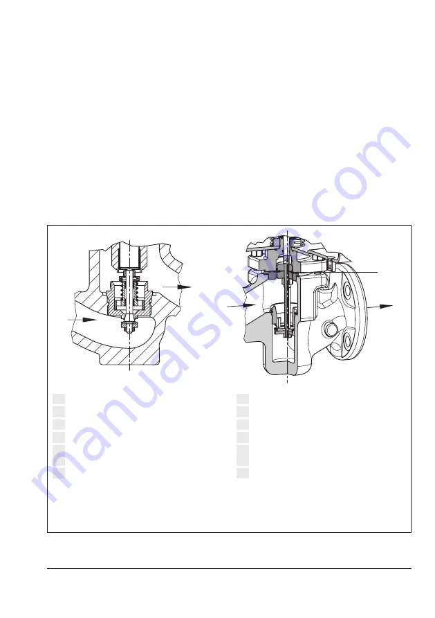
In the version with pressure balancing, the 
forces produced by the upstream and down-
stream pressures acting on the plug are elim-
inated by the balancing diaphragm (10). 
The plug is fully balanced.

p

1

p

2

p

1

p

2

10

1

Valve body

2 Seat
3 Plug
4 Plug stem

5 Diaphragm plate with operating dia-

phragm

6 Actuator housing

7 Set point spring
8

Set point adjuster (screw SW 27)

9

Control line connection, G ¼ fitting

10

Balancing diaphragm

11 Leakage line connection (special version), 

G ¼ fitting

12

Cap

Fig. 4: 

Type 2405 Pressure Reducing Valve 

without pressure balancing · K

VS


0.016 to 1 · Flow-to-close

Fig. 5: 

Type 2405 Pressure Reducing Valve with 

pressure balancing · K

VS

 6.3 to 32

Содержание 2405 Series

Страница 1: ...Translation of original instructions EB 2520 EN Type 2405 Pressure Reducing Valve Self operated Pressure Regulators Edition December 2022...

Страница 2: ...st you in mounting and operating the device safely The instructions are binding for handling SAMSON devices The images shown in these instructions are for illustration purposes only The actual product...

Страница 3: ...g and lifting 19 4 3 Storage 20 4 4 Preparation for installation 20 5 Mounting and start up 21 5 1 Installing the valve into the pipeline 21 5 1 1 Installation conditions 21 5 1 2 Mounting orientation...

Страница 4: ...damage caused by external forces or any other external factors Refer to the technical data and nameplate for limits and fields of application as well as possible uses Reasonably foreseeable misuse Th...

Страница 5: ...injury or property damage plant operators and operating personnel must prevent hazards that could be caused in the regulator by the process medium the operating pressure or by moving parts by taking...

Страница 6: ...ements warnings and caution notes Furthermore operating personnel must be familiar with the applicable health safety and accident prevention regulations and comply with them Safety features The Type 2...

Страница 7: ...uges etc 1 1 Notes on possible severe personal injury DANGER Risk of bursting in pressure equipment Valves and pipelines are pressure equipment Improper opening can lead to valve components bursting O...

Страница 8: ...d pipelines may get very hot or cold and cause burn injuries Allow components and pipelines to cool down or warm up to the ambient tempera ture Wear protective clothing and safety gloves Damage to hea...

Страница 9: ...use leakage Observe the specified tightening torques Risk of regulator damage due to the use of unsuitable lubricants The lubricants to be used depend on the regulator material Unsuitable lubricants m...

Страница 10: ...32 to 50 Fig 1 Nameplate 1 Max perm operating pressure at the actuator 2 Material number configuration ID 3 Type 4 Production number 5 KVS CV 6 Set point range 7 Valve size 8 Pressure rating 9 Perm di...

Страница 11: ...the device 2 2 Location of the nameplate Location of the nameplate Fig 2 Nameplate of Type 2405 Regulator 2 3 Material identification number See the nameplate 11 body material For more details on the...

Страница 12: ...regulator and transmitted over an external control line to the control line connection 9 on the actua tor housing 6 where it is converted into a positioning force by the diaphragm plate with operating...

Страница 13: ...2 10 1 Valve body 2 Seat 3 Plug 4 Plug stem 5 Diaphragm plate with operating dia phragm 6 Actuator housing 7 Set point spring 8 Set point adjuster screw SW 27 9 Control line connection G fitting 10 Ba...

Страница 14: ...to temperatures of 60 C Table 1 Temperature range from 0 to 150 C for un balanced versions with FKM diaphragm and FKM soft seal Leakage class The soft seated regulator has the leakage class IV accord...

Страница 15: ...150 C 2 Leakage class acc to IEC 60534 4 Soft seated minimum Class IV Conformity Set point ranges 5 to 15 mbar 5 10 to 30 mbar 5 25 to 60 mbar 5 50 to 200 mbar 0 1 to 0 6 bar 0 2 to 1 bar 0 8 to 2 5 b...

Страница 16: ...hout balancing 318 366 With balancing 345 370 Actuator D 380 mm A 640 cm 50 to 200 mbar Height H Without balancing 318 366 With balancing 345 370 Actuator D 285 mm A 320 cm 0 1 to 0 6 bar Height H Wit...

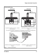
Страница 17: ...320 cm Control line connection G for A 640 and 1200 cm The control line connection is turned by 90 in the drawing The connection is normally located opposite the side with the arrow indicating the di...

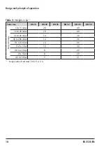
Страница 18: ...alve size DN 15 DN 20 DN 25 DN 32 DN 40 DN 50 Set point range 5 to 15 mbar 28 40 10 to 30 mbar 18 40 25 to 60 mbar 14 30 50 to 200 mbar 14 26 0 1 to 0 6 bar 14 26 0 2 to 1 bar 10 22 0 8 to 2 5 bar 8 2...

Страница 19: ...kaging from the device 2 Dispose of the packaging in accordance with the valid regulations 4 2 Transporting and lifting Due to the low service weight lifting equip ment is not required to lift and tra...

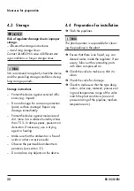
Страница 20: ...p spaces prevent con densation If necessary use a drying agent or heating Make sure that the ambient air is free of acids or other corrosive media Observe the permissible ambient tem peratures see sec...

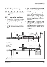
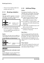
Страница 21: ...ng point 10 slope to pressure tapping point 1 Shut off valve 2 Pressure gauge 3 Strainer 4 Control line Fig 7 Installation example Make sure the direction of flow matches the direction indicated by th...

Страница 22: ...pipelines NOTICE 5 1 3 Additional fittings Strainers We recommend installing a strainer e g SAMSON Type 2 N upstream of the regula tor It prevents solid particles in the process medium from damaging t...

Страница 23: ...connection at least 6 x DN Optionally a ready mounted control line is available for set point ranges 0 8 to 2 5 bar 2 to 5 bar and 4 5 to 10 bar This option must be specified in the order see Fig 10...

Страница 24: ...ected and free of dirt The cross sec tional area of flow must be open 2 Slowly open the shut off valves on the upstream pressure side 3 Open all the valves on the consumer side downstream of the regul...

Страница 25: ...ersonal injury due to residual pro cess medium in the valve While working on the valve residual me dium can flow out of the valve and depend ing on its properties cause personal injury e g chemical bu...

Страница 26: ...MSON s After sales Service for infor mation on spare parts lubricants and tools Risk of burn injuries due to hot or cold com ponents and pipelines Depending on the process medium valve components and...

Страница 27: ...gloves and eye protection Risk of burn injuries due to hot or cold com ponents and pipeline Valve components and the pipeline may be come very hot or cold Risk of burn injuries Allow components and p...

Страница 28: ...lation drawing showing the exact location of the regulator and all the ad ditionally installed components shut off valves pressure gauge etc 8 Disposal SAMSON is a producer registered at the following...

Страница 29: ...formity in compliance with Directive 2016 No 1105 on page 37 UKCA declaration of conformity in compliance with Directive 2008 No 1597 for Type 2405 Regulator on page 39 10 1 Information on the UK sale...

Страница 30: ...CF8M NPS 1 2 Class 150 all fluids Control valve 3214 DIN EN body EN GJL 250 DN 65 125 PN 16 fluids G2 L2 L11 DIN EN body EN GJS 400 18 LT DN 50 80 PN 25 fluids G2 L2 L11 ANSI body A126 B NPS 3 4 Clas...

Страница 31: ...all fluids 42 2421 RS DIN EN body 1 0619 1 4408 1 4571 and 1 4401 1 4404 DN 32 50 PN 16 all fluids DIN EN body 1 0619 1 4408 1 4571 and 1 4401 1 4404 DN 32 40 PN 25 all fluids ANSI body A216 WCC A351...

Страница 32: ...f the laws of the Member States relating to the making available on the market of pressure equipment 2014 68 EU of 15 May 2014 Applied conformity assessment procedure for fluids according to Article 4...

Страница 33: ...EN GJS 400 18 LT DN 100 150 PN 25 fluids G2 L2 L11 DIN EN body 1 0619 and 1 4408 DN 65 250 PN 16 all fluids DIN EN body 1 0619 and 1 4408 DN 50 250 PN 25 all fluids DIN EN body 1 0619 and 1 4408 DN 32...

Страница 34: ...N 40 all fluids ANSI body A126 B NPS 6 16 Class 125 fluids G2 L2 L11 ANSI body A216 WCC und A351 CF8M NPS 2 16 Class 150 all fluids ANSI body A216 WCC und A351 CF8M NPS 2 10 Class 300 all fluids 2331...

Страница 35: ...he European Parliament and of the Council on the harmonization of the laws of the Member States relating to the making available on the market of pressure equipment 2014 68 EU of 15 May 2014 Applied c...

Страница 36: ...36 EB 2520 EN Certificates...

Страница 37: ...to Article 4 1 c ii acc to PE S R 2016 The object of the declaration described above is in conformity with the relevant Union har monization legislation Legislation STATUTORY INSTRUMENTS 2016 No 1105...

Страница 38: ...tion Legislation STATUTORY INSTRUMENTS 2016 No 1105 CONSUMER PROTECTION HEALTH AND SAFETY The Pressure Equipment Safety Regulations 2016 PE S R 2016 2022 Applied conformity assessment procedure for fl...

Страница 39: ...f conformity Machinery components can be mounted onto the above specified final ma chinery if they comply with the specifications and properties defined by SAMSON Manual H 02 Ap propriate Machinery Co...

Страница 40: ...2023 01 19 English SAMSON AKTIENGESELLSCHAFT Weism llerstra e 3 60314 Frankfurt am Main Germany Phone 49 69 4009 0 Fax 49 69 4009 1507 samson samsongroup com www samsongroup com EB 2520 EN...

Отзывы: