Translation of the original operating instructions
Electrical position indicators type 024.85/024.86/024.87
© 1994 - 2021 SED Flow Control
45
BA210008 Version:
a
Vo
rl
ag
e
: d
o
k360 (
c)
Figure 6 Wiring diagram for 024.87
5.3.
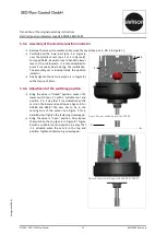
Assembly & disassembly of the electrical position indicator
Danger
Check the device for correct installation before initial operation!
Compare the type plate with your order. Proper assembly and function can only be guaranteed if the control
unit fits the valve
Warning
The operating instructions contain important information for your safety!
Failure to heed these instructions can lead to dangerous situations.
The operating instructions must be read and understood.
Only use functional, suitable and safe tools! Assembly, disassembly and initial operation are only to be
carried out by trained personnel.
Remove the protective cap/existing accessories from the top of the actuator. Accessories are screwed
in, whereas the cover can either be pressed or screwed in. For further details, please check the
operating instructions of the accessories.
When removing the accessories, it must be ensured that no foreign objects enter the actuator.
Protect the device from sunlight.
The following information provide assistance during the installation and operation of the electrical position
indicator in humid environments.
▪
Lay cables and pipes in such a way that condensate or rainwater hanging on pipes cannot run in cable
glands of the electrical position indicators.
▪
Check all cable glands for fixed seat.
▪
Check sealing elements for correct fit, wear and damage during each installation.
customer ports


