


18
Special Chuck
Special Ch
uck
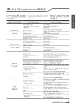
3-6 검사
설치 순서에 따르지 않을 경우 작동에 이상이
발생할 수 있습니다. 작동에 이상이 있을 시 척
을 사용하면 부품이 비정상적으로 마모되어 수
명이 크게 단축될 수 있습니다.
설치가 완료되면 최소 작동압력을 확인하십시
오. 압력이 너무 높으면 척을 분해하고 문제를
해결하십시오.
아이볼트를 사용하여 설치하는 경우 설치가 끝
난 후 아이볼트를 제거하십시오. 아이볼트를
조립한 상태에서 척을 회전시키면 신체나 옷에
걸려 상해를 입을 수 있습니다.
3-7 발란스
척을 추가로 가공하거나 지그가 장착된 경우
발란스 작업을 하시기 바랍니다. 발란스가 맞
지 않은 척은 진동을 유발하고 필요한 가공 정
확도를 유지하지 못하게 합니다. 불균형한 공
작물을 가공할 시 공작물의 편심질량을 고려
하여 척을 저속으로 돌리시기 바랍니다. 편심
질량으로 인한 원심력이 TOP JAW에 적용되
기 때문입니다.
3-6 Examination
Failure to follow the installation
sequence may cause malfunc-tion.
If the chuck is used during operation,
the parts may be worn abnormally
and the lifespan may be significantly
reduced.
When installation is complete, check
the minimum working pressure. If the
pressure is too high, disassemble and
solve the chuck.
When installing using eye bolts, re-
move the eye bolts after instal-lation
is complete. If the chuck is rotated
while the eyebolt is assembled, it may
cause injury to the body or clothes.
3-7 Balance
If the chuck is additionally machined
or a jig is installed, balance it. An
unbalanced chuck causes vibration
and prevents maintaining the required
machin-ing accuracy. When machin-
ing an unbalanced workpiece, take
the eccentric mass of the workpiece
into account and turn the chuck at a
low speed. This is because centrifugal
force due to eccentric mass is applied
to TOP JAW.
3-6 考试
不按照安装顺序,造作时可能会出现
问题。要是运转出现问题时继续使用
卡盘,可能会使配件非正常磨损,缩
短寿命。
安装后请确认最小运转压力。要是压
力过于高,请分解卡盘并解决问题。
使用吊环螺栓安装时,安装结束后请
解除吊环螺栓。在装配吊环螺栓的状
态下,旋转卡盘的话,可能会引身体或
衣服而受伤。
3-7 余额
添加加工卡盘或安装好钻模时,请进
行稳定的操作。不平衡的卡盘会引起
震动,使必要的加工精度无法维持。
加工不均衡的工作物时,请考虑到工
作物的偏心质量,而将卡盘转低速。
因为偏心质量引起的离心力影响到
TOP卡爪。
Содержание PHD
Страница 1: ...Special Chuck PHD PHDN Instruction Manual...
Страница 28: ...28 Special Chuck Special Chuck 5 1 2 99 A S TEL 032 822 4811 FAX 032 822 4377 1544 3122 PHD PHDN 12...
Страница 31: ......


