


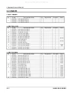
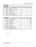


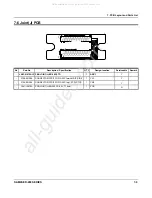


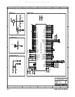


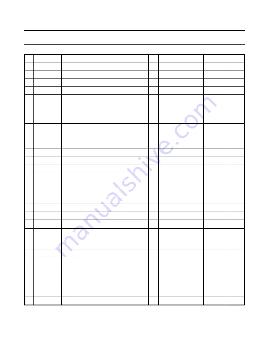
7. PCB Layout and Parts List
7-4
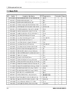
SAM4S ER-280 SERIES
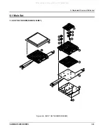
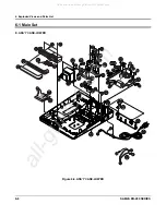
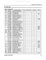
7-1 Main PCB
No
Part-No
Description / Specification
Q'TY
Design-location
Serviceable
Remark
- 2008-000020
R-CHIP:470OHM,5%,1/10W,1608
5
R1,R84,R86,R105,R115
N
- 2008-000026
R-CHIP:1KOHM,5%,1/10W,1608
6
R2,R27,R32,R38,R83,R118 N
- 2008-000030
R-CHIP:2KOHM,5%,1/10W,1608
2
R120,R138
N
- 2008-000031
R-CHIP:2.2KOHM,5%,1/10W,1608
1
R80
N
- 2008-000037
R-CHIP:4.7KOHM,5%,1/10W,1608
32
R16,R19,R21,R28,R33,
R39,R42,R43,R46,R47,
R61,R70-R73,R75,R76,
R78,R79,R85,R88,R90,
R99,R102,R109,R111,
R117,R131,R133,R139,
R140,R142
N
- 2008-000044
R-CHIP:10KOHM,5%,1/10W,1608
34
R10,R23,R24,R29,R30,
R34,R36,R41,R49,R53,
R68,R69,R74,R81,R87,
R89,R91,R93,R103,R112,
R114,R116,R119,
R122-R130,R135,R141
N
- 2008-000045
R-CHIP:12KOHM,1%,1/10W,1608,1%
3
R77,R95,R121
N
- 2008-000046
R-CHIP:15KOHM,5%,1/10W,1608
5
R4,R6,R54,R132,R137
N
- 2008-000051
R-CHIP:27KOHM,5%,1/10W,1608
3
R15,R108,R136
N
- 2008-000054
R-CHIP:36KOHM,1%,1/10W,1608,1%
2
R96,R134
N
- 2008-000063
R-CHIP:100KOHM,5%,1/10W,1608
2
R11,R50
N
- 2008-000065
R-CHIP:150KOHM,5%,1/10W,1608
4
R5,R13,R51,R66
N
- 2203-000192
C-CERAMIC,CHIP:100nF,+80-20%,50V,Y5V,TP,
2
C17,C47
N
- 2204-000003
C-CERAMIC,CHIP:15pF,5%,50V,1608
1
C58
N
- 2204-000004
C-CERAMIC,CHIP:22pF,5%,50V,1608
2
C54,C55
N
- 2204-000010
C-CERAMIC,CHIP:100pF,5%,50V,1608
11
C3-C6,C11,C14,C15,C40,
C46,C49,C72
N
- 2204-000028
C-CERAMIC,CHIP:100nF,+80-20%,25V,Y5V,160
41
C1,C2,C7,C10,C13,C18,
C19,C21,C24,C30,C32,C33
C36-C39,C41-C45,C48,
C50-C53,C56,C57,
C59-C65,C68-71,C75,C76
N
- 2204-000029
C-CERAMIC,CHIP:1uF,+80-20%,16V,Y5V,1608
2
C73,C74
N
- 2801-003382
CRYSTAL-SMD:14.7456MHZ,SX-1,18pF
1
X1
Y
- 3711-004121
WAFER;BOX-HEADER,1R,
6P,1.25mm,SMD,
1
CN3
Y
- 3711-004123
WAFER;BOX-HEADER,1R,
8P,1.25mm,SMD,
1
CN8
Y
- 3711-004125
WAFER;BOX-HEADER,1R,
10P,1.25mm,SMD,
1
CN4
Y
3712-000060
CONNECTOR-SD
CARD:SMD,12P,RoHS
1
CN14
Y
JK41-10690A
PCB-MAIN:ER-280,FR-4,2L,T1.6mm
1
PCB
N
All manuals and user guides at all-guides.com
all-guides.com
Содержание ER-Series
Страница 24: ...3 Installation and Operation 3 10 SAM4S ER 280 SERIES MEMO All manuals and user guides at all guides com...
Страница 30: ...4 Disassembly and Assembly 4 6 SAM4S ER 280 SERIES MEMO All manuals and user guides at all guides com...
Страница 53: ...SAM4S ER 280 SERIES 7 1 7 PCB Layout and Parts List 7 1 Main PCB All manuals and user guides at all guides com...
Страница 64: ...8 Block Diagram 8 2 SAM4S ER 280 SERIES MEMO All manuals and user guides at all guides com...
Страница 86: ...10 20 SAM4S ER 280 SERIES MEMO All manuals and user guides at all guides com a l l g u i d e s c o m...


