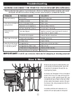
Operating Instructions
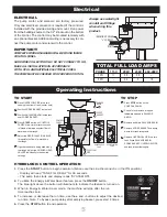
GUSHER HEAD
VALVE
RECIRCULATION
VALVE
3
B
C
SALVAGE
BASIN
CONTROL
PANEL
4 A
2
D
SCRAP
BASKET
1
E
OVERFLOW
PIPE
6
5
TO START
l
1
Place OVERFLOW PIPE into drain
opening in bottom of tank (center hole).
l
2
Position SCRAP BASKET inside tank.
l
3
Position SALVAGE BASIN inside tank
over SCRAP BASKET.
l
4
Press START button on CONTROL
PANEL. Allow time for reservoir tank
to fill and maintain a constant flow of
water down the trough.
l
5
Adjust the RECIRCULATION VALVE
to regulate the flow of water down
the trough.
l
6
If gusher heads are being used along
the trough, adjust the GUSHER HEAD
VALVES individually to the desired
settings.
TO STOP
l
A
Press STOP button on the
CONTROL PANEL.
l
B
Check for and remove dropped
tableware trapped in SALVAGE
BASIN.
l
C
Remove and drain SALVAGE BASIN.
l
D
Remove SCRAP BASKET and dump
waste into trash receptacle.
l
E
Remove OVERFLOW PIPE to drain
tank.
Rinse SALVAGE BASIN,
SCRAP BASKET, OVERFLOW PIPE,
and tank interior thoroughly.
HYDROLOGIC CONTROL OPERATION
1. Press the START button to begin operation. (Make sure the Line Disconnect is in the ON position)
• Display will read “TANK FILL DELAY” for 30 seconds.
• The pump then starts and display reads “SYSTEM ON”.
2. To utilize the Energy & Water Saver feature, press the ON/OFF button.
The blue light above the button will illuminate to indicate the feature is turned on.
3. When in Energy & Water Saver mode, the machine will stop after the run
time reaches zero.
4. To increase or decrease the run time, use the + and - buttons to adjust the desired
run time. Note: To bypass pump delay after emptying basket, press start 2 times.
5. Press the STOP button to end operation.
5
Electrical
INCOMING POWER
1
/
2
" CONDUIT
PUMP
ELECTRICAL
The pump motor and solenoid are factory pre-wired.
Only one electrical connection is required if the control is
installed with the provided wiring and mount. Run power
from the building source to the 1/2” knockout on the bottom
of the control. The control may be mounted remotely with
an optional bracket. Additional wiring is necessary to con-
nect the pump motor and solenoid to the control.
IMPORTANT!
COMPLETE WIRING DIAGRAMS WILL BE FOUND INSIDE
CONTROL PANEL.
HARD WIRE COLLECTOR ONLY. DO NOT CONNECT TO GFI.
MAKE ALL INSTALLATIONS IN ACCORDANCE
WITH LOCAL AND NATIONAL ELECTRICAL CODES.
THE PUMP MUST BE CHECKED FOR PROPER ROTATION.
Always use watertight
conduit and fittings
when wiring this
product.
PHASE 115V 208V 230V 460-480V
1 PH
11
5.5
5.5
–
3
PH – 3.2 3 1.5
TOTAL FULL LOAD AMPS


