Tel: 886.909 602 109 Email: [email protected]
13
3.5 Introduction of Interface Parameters
3.5.1 Main interface
(
Control and track display interface
)
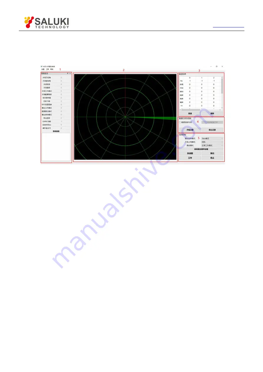
Main interface is shown in Figure 3.2.
Figure 3.2 Main interface
“1”
is the system status, and the system information such as the current azimuth and elevation angle of the radar is
displayed in real time. The “System Information” box will display the error of the radar system. For the common error
handling method, refer to Section 4.1.
“2”
is the track display frame. The track map is shown in Fig.8. The green fan shape is the current beam direction of
the radar. The original track is displayed as a white partial transparent point. The incomplete batch track is displayed
in gray. Displayed in yellow, the selected track is displayed in red, and the corresponding information of the selected
track is displayed at the sequence number 0 of the track information box at "3";
“3”
is the track information, where the sequence number 0 shows the selected track. The track information includes:
No (track number), distance, azimuth (degree), pitch (degree), speed (near the radar is positive, Far away from
negative), height (m), amplitude, longitude, latitude, altitude, etc.;
“4”
is the data recording and playback function area;
“5”
is the system control function area, "Radar task mode" is used to select the radar mission mode, there are "3km
mode", "5km mode", etc. (Note: some old models may need to upgrade hardware or programs to have "5km" "Mode"
and other functions; the "Clutter Map" button is used to generate the clutter map. During the generation of the clutter
map, please do not stop the radar or click other buttons on the interface; the "Reset" function is used to control the
radar reset; "Work" and The Stop button is used to control the start and stop of the radar.
Note:
After clicking the “Stop” button, “Antenna Power-on Mode” will be automatically set to “Standby”. If you need to
start normally, please select “Power-on and Send-up” again and click the “Work” button.


