17
•
The reverse open circuit feature [NO] can be modified at the fac-
tory or later on-site by our TSS.
Except for specific cases, we advise against this type of connec-
tion in view of the purpose of the EPO button, since it will not act
upon an emergency request if either of the two cables that run
from the button to the UPS are disconnected [damaged].
By contrast, this anomaly would immediately be detected in a
closed EPO circuit, with the inconvenience of an unexpected cut
in the powering of the loads, but a guarantee of effective emer-
gency functionality.
•
In order to recover the normal operating status of the UPS, it is
necessary to insert the connector with the jumper in its recep-
tacle or to deactivate the EPO button and later eliminate the
EPO status on the control panel. The device will be operational.
5.2.5. Communication port.
5.2.5.1. RS232 port and USB interface.
•
The communications line [COM] constitutes a very low
voltage safety circuit. To preserve the quality, it must be
installed separately from other lines carrying dangerous voltages
(power distribution line).
•
The USB interface is useful for the monitoring software and up-
dating the firmware.
•
It is not possible to use both RS232 and USB ports at the same
time.
•
The RS232 port consists of serial data transmission, so that a
large amount of information can be sent via a communication
cable of only 3 wires.
•
The USB port offers the ‘smart battery’ feature, supported by
the HID (human interface device) power device class, without
the need for software installation. Operating systems such as
Windows/Linux/Mac OS include management and monitoring
of the energy of this function. When a computer is connected to
the UPS via the USB port, the UPS is recognised by the operating
system as a ‘HID UPS battery,’ and the user can configure the
action to be taken in the event of a low battery alarm, such as
stopping the computer automatically. This feature is ideal for
powering network-attached storage -NAS- systems with a UPS.
The USB port is compatible with the USB 1.1 protocol for com-
munication software.
Pin #
Description
Input / Output
2
TXD for RS232
Output
3
RXD for RS232
Input
5
GND for RS232
Ground
Table 3.
DB9, RS232 connector pinout
5 1
9 6
2 1
3 4
Fig. 6.
DB9 connectors for RS232 and USB
5.2.5.2. Smart slot.
•
The UPS has a slot behind the cover indicated on the device
views as ‘Smart Slot’ that enables any of the following cards
to be inserted:
Relay interface to terminals.
SNMP adapter.
•
The corresponding documentation is supplied with each option.
Read it before starting installation.
5.2.6. Protection against voltage spikes for the modem /
ADSL / Fax / ... line.
•
The communications line -COM- constitutes a very low
safety voltage circuit. To conserve quality, it must be
installed separately from other lines that carry dangerous
voltages (power distribution line).
•
Connect the main line for the Modem / ADSL / Fax / ... to the
RJ45 connector of the equipment, identified as "Input".
•
Connect the Modem / ADSL / Fax / ... itself to the RJ45 connector
of the unit, identified as "Output".
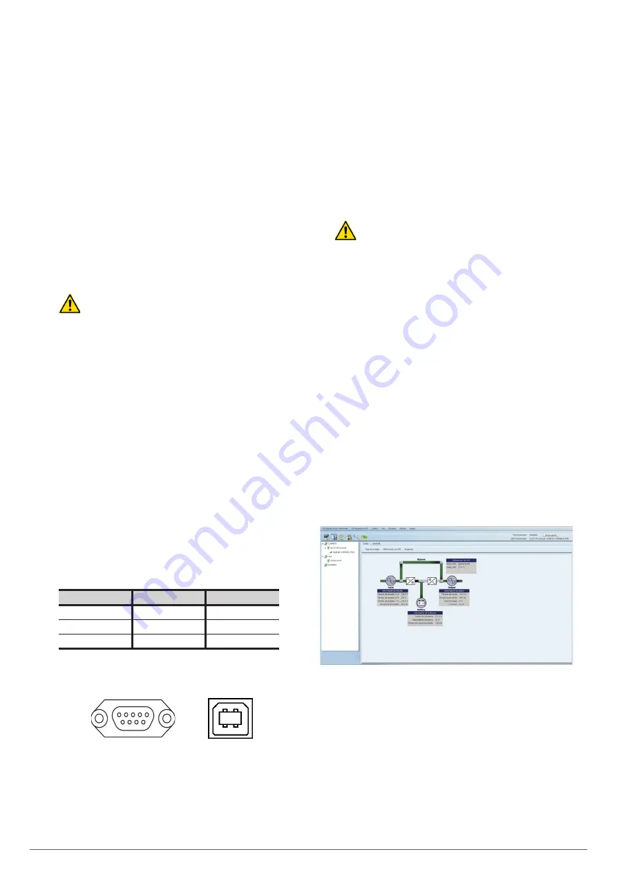
5.2.7. Software.
•
Download of free ViewPower software.
ViewPower is a UPS monitoring software which provides a user-
friendly interface for monitoring and control. It features an auto
shutdown function for systems consisting of several PCs in case
of power failure. The software enables users to monitor and
control any UPS in the same LAN through an RS-232 or USB
communications port, regardless of how far away they are from
each other.
•
Installation procedure:
Go to the web page:
http://support.salicru.com
Select the required operating system and follow the instruc-
tions described on the web page to download the software.
Fig. 7.
View of the monitoring software’s main screen.
SLC TWIN PRO2
UNINTERRUPTIBLE POWER SUPPLY (UPS)
USER MANUAL


