USER MANUAL
SAJ SOLAR INVERTER
33
34
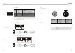
Pin Number
Wire color
Function
2
3
4
5
6
7
8
1
Orange
White-orange
NC
NC
NC
NC
NC
NC
RS485-A
RS485-B
White-green
Blue
White-blue
Green
White-brown
Brown
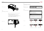
1.LED indicator as the alarm/fault indicator. When relay is in normal close
contact (NC) and no alarm/fault occurs, LED indicator is on; When there is
fault occurs, relay is in normal open contact (NO), LED indicator is off.
The inverter is integrated with RS485 communication terminal and meter
communication terminal. RS485 communication terminal is mainly for mul-
tiple inverters communication which can be connected in a daisy chain
manner. Meter communication terminal is mainly for data interaction be-
tween monitoring device and inverter.
Note: Meter and RS485 communication have two kinds of interface, one is
RJ45 terminal, another is terminal block, these two ports perform the same
function but with different wiring. Please choose either one interface for
cable connection.
Multiple inverter dry contact connection
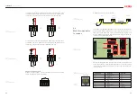
2.LED indicator as the alarm/fault indicator. When relay is on normal open
contact (NO) and no alarm/fault occurs, LED indicator is off; When there is
fault occurs, relay is on normal close contact (NC), LED is on.
Emergency stop dry contact:
When DI+ contact and DI- contact are shorted by external controlled
switch, the inverter will stop immediately.
COM1
NC1
NO1
COM1
NC1
NO1
COM1
NC1
NO1
COM1
NC1
NO1
DI + DI- DI+ DI-
Inverter 1
Inverter 2
Inverter 3
Switch
150.00
A1 B1 PE A1 B1 PE
USB
L
CN9
CN10
H
A2 B2 PE A2 B2 PE
METER
LOCAL STOP
DRM
ALARM
NC NO COM
RS485
METER
DI+ DI- DI+ DI-
DI+ DI- DI+ DI-
DI+ DI- DI+ DI-
RS485 DIP swich
Meter (RJ45) port
Meter (Terminal block)
port
RS485 (Terminal block)
port
Met
er (T
erminal block) port
RS485
RS485
DI+ DI- DI+ DI-
OFF
120Ω
NO
OFF
120Ω
NO
OFF
120Ω
NO
RS485
SW1
CAN
SW3
METER
SW2
C1
RT2
M9
M12
RT1
LOCAL STOP
5.6
RS485 Communication
Connection
Table 5.9
RS485 pin port description
Fig 5.15
Relay is in normal close contact
Fig 5.16
Relay is in normal open contact
Fig 5.18
Multiple inverter dry contact
Fig 5.19
RS485 communication
Fig 5.17
Emergency stop dry contact
Fig 5.20
RS485 pin


