


USER MANUAL
SAJ SOLAR INVERTER
31
32
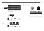
Position
Description
B
C
D
E
A
DIP Switch
Alarm Output Dry Contact
Emergency Stop Dry Contact
Meter Output
Connecting Procedures:
1. Tighten the lock screws on positive and negative connector.
2. Strip the insulation of the positive and negative cables with 8-10mm
length.
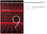
The inverter is integrated with alarm output dry contact and emergency
stop dry contact.
Alarm output dry contact:
Relay can be set to normal open contact (COM&NO) or normal close con
-
tact (COM&NC), when inverter is in alarm/fault state, the fault status can
be indicated by LED indicator or other external display device.
USB
L
CN9
CN10
H
150.00
A2 B2 PE A2 B2 PE
A1 B1 PE A1 B1 PE
METER
LOCAL STOP
DRM
ALARM
RS485
METER
USB
Alarm output
dry contact
Emergency stop
dry contact
L
CN9
CN10
H
150.00
A2 B2 PE A2 B2 PE
A1 B1 PE A1 B1 PE
METER
LOCAL STOP
DRM
ALARM
RS485
METER
1. Positive cable
2. Negative cable
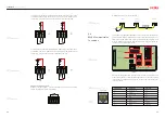
OFF
120Ω
NO
OFF
120Ω
NO
OFF
120Ω
NO
RS485
SW1
CAN
SW3
METER
SW2
C1
RT2
M9
M12
RT1
NC NO COM
RS485
RS485
DI+ DI- DI+ DI-
NC NO COM
RS485
RS485
DI+ DI- DI+ DI-
OFF
120Ω
NO
OFF
120Ω
NO
OFF
120Ω
NO
RS485
SW1
CAN
SW3
METER
SW2
C1
RT2
M9
M12
RT1
1
1
4.Insert the positive and negative connectors into positive cable and nega
-
tive cable whose insulated enclosure has been stripped off, and crimp
them tightly with a wire crimper. Make sure that the withdrawal force of
the pressed cable is bigger than 400N.
5. Plug in the pressed positive and negative cables into relevant insulated
enclosure, a “click” should be heard or felt when the contact cable assem
-
bly is seated correctly.
6. Fasten the lock screws on positive and negative connectors into respec
-
tive insulated enclosure and make them tight.
3.Feed the positive and negative cables into corresponding lock screws.
7.Make sure the DC switch is at OFF position
8.Connect the positive and negative connectors into positive and negative
DC input terminals of the inverter, a “click” should be heard or felt when
the contact cable assembly is seated correctly.
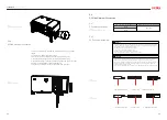
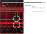
1. Connection port
RS485 Communication Port
Fig 5.8
Striping off the insulation skin of cables
Fig 5.9
Inserting cables to lock screws
Fig 5.10
Inserting crimped cables to connectors
Fig 5.12
Plug in connectors
Fig 5.11
Securing the connectors
Table 5.8
Terminal description
Fig 5.13
Communication terminal overview
Fig 5.14
Dry contact overview
5.5.1
Communication
Terminal Overview
5.5
Communication
Connection
5.5.2
Dry Contact Connection


