background image

3

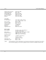
Technical Specification

RT4722

Duplex spurious resp. att.

More than 70 dB

Duplex desensitation

Below 3 dB

Intermodulation att.

More than 68 dB

Co-channel rejection

Better than -10 dB

Adj. ch. selectivity

More than 70 dB

Blocking

More than 90 dBµV

Transmitter
RF output power *

High 25W + 0 dB to -0.5 dB
Low

0.9W +0.5 dB to - 1 dB

Adj. ch. power

Below -70 dBc

Spurious radiation

Below 0.25 µW

Cabinet radiation

Below 0.25 µW

AF response

+ 6 dB/octave

Distortion

Below 5%

Signal/noise ratio

Better than 40 dB

DSC Facilities:
DSC operation

According to Rec. ITU-R M.541-6
and Rec. ITU-R M.689-2

DSC protocol

According to Rec. ITU-R M.493-7 class A

Navigator interface

NMEA 0183, GGA,GLL,ZDA
NMEA input current 8mA type

Symbol error rate
below 1*10

-2

 at

-119 dBm or 0.25 µV p.d.

Modulation

1700 Hz ± 400 Hz
1200 baud ± 30 ppm

Frequency error

Below ± 1 Hz

Residual DSC-mod.

Below - 26 dB

* Note:

The transmitter has a built in temperature sense function that will reduce the output power from 25W to
1W if the radio is getting too hot. This may happen if there is no free air circulation around the radio.

9945

Содержание RT4722

Страница 1: ...SAILOR RT4722 VHF DSC DUPLEX Installation Manual ...

Страница 2: ...rements within the concept of GMDSS as to operation of equipment and basic understanding of the systems is an extremely important factor for the overall success ful implementation of GMDSS As a unique initiative for GMDSS solutions we can supply a complete software training programme for on board training to be used as preparation in order to fulfil the GMDSS requirements for obtaining the General...

Страница 3: ...ndset Connection 8 2 5 Loudspeaker Connection 9 2 6 Connectors 9 2 6 1 SPARC Bus Cable 10 2 6 2 Options Connector H4992 11 2 7 Cable Length 12 2 7 1 Power Cable 12 2 8 Electrical Connections 12 2 8 1 Power Connectors 12 2 8 2 Interconnection Cable Specification For VHF Printer Connection 13 2 9 Compass Safety Distance 13 2 10 Test Procedure TX RX DSC Call 14 ...

Страница 4: ... MHz 157 425 MHz Rx 160 625 MHz 163 6 MHz Operating modes Simplex Semi duplex duplex Modulation G3EJN for telephony receiver G2B for DSC signaling Frequency stability 10 ppm opt 5 ppm Aerial connectors Standard 50 ohm female SO239 Temperature range 15 C to 55 C Supply voltage 13 2V DC Nominal Supply range 10 8V DC to 15 6V DC Supply current Stand by 0 14A Transmitter on 1 5A Low power Transmitter ...

Страница 5: ... Distortion Below 5 Signal noise ratio Better than 40 dB DSC Facilities DSC operation According to Rec ITU R M 541 6 and Rec ITU R M 689 2 DSC protocol According to Rec ITU R M 493 7 class A Navigator interface NMEA 0183 GGA GLL ZDA NMEA input current 8mA type Symbol error rate below 1 10 2 at 119 dBm or 0 25 µV p d Modulation 1700 Hz 400 Hz 1200 baud 30 ppm Frequency error Below 1 Hz Residual DSC...

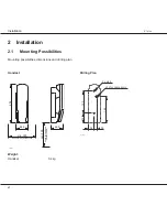
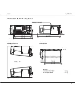
Страница 6: ...ities Mounting possibilities dimensions and drilling plan Handset Drilling Plan 4 0 35999 68 5 66 5 209 min 300 Space for handset access min 200 Space for cable and handset cable 4 0 35556 34 123 52 5 2 x ø4 5 ø12 for cable entry 144 13 5 Weight Handset 0 4 kg ...

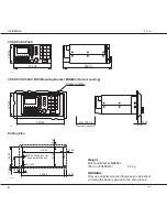
Страница 7: ...DUPLEX With Mounting Bracket 36846 200 00 231 00 100 00 110 00 max 280 Bracket Standard Mounting Option Drilling plan 36847 Tilting 6 4 x ø4 14 25 11 00 76 50 98 50 209 00 180 50 Weight VHF DSC DUPLEX 3 9 kg Mounting Bracket 0 7 kg ...

Страница 8: ...0 125 00 Space for Cable entry min 100 00 16 00 Drilling Plan 4 0 36006 62 50 4 x M4 230 00 10 00 R7 00 Make a cut for handset cable entry 104 00 10 50 215 00 105 00 20 00 17 50 10 00 Weight Mounting Bracket MB4994 Part no 80499410 0 2 kg WARNING Only use original screws otherwise you risk short circuiting the battery ground to the ship ground 9945 ...

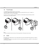
Страница 9: ...V AC operation an external power supply with the type number N163S must be used together with N420 Fuse The fuse is a standard 10A mini car fuse There is a spare fuse in the power cable connector 2 3 Aerial All common 50 ohm aerials which cover the used frequency range with a reasonable standing wave ratio maximum 1 5 can be used The aerial is connected to the set by means of a 50 ohm coaxial cabl...

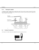
Страница 10: ...ear as possible as illustrated below Note that the primary transceiver aerial must be placed at a higher level than the channel 70 receiver aerial Channel 70 receiver aerial transceiver aerial 37035 Primary 2 4 Handset Connection The handset is connected directly to the HANDSET plug at the back of the VHF set 35405 Rx Tx 12V DC SPARC BUS OPTION PRINTER HANDSET 9945 ...

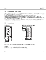
Страница 11: ... signals LS_1 and LS_1 or LS_2 and LS_2 depending on which speaker selection is made by the control unit s 2 6 Connectors Handset Hook SPARC Bus Connection Box H4991 35348 _ON Term ON VDC 12 LS_1 LS_1 LS_2 LS_2 BAT AF AF _AF RX BAT _AF RX SPARC _ON SUPPLY VDC 12 RX_AF RX_AF 12VDC BAT AF BAT AF SPARC LS_2 LS_2 _1 LS _1 LS SUPPLY HOOK Connection 32262 SPARC SPARC 12VDC X2 5 1 2 3 4 13 14 15 X3 6 7 8...

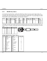
Страница 12: ... 2 100 metres 56 114 12 Volt 2x8 Transceiver HOOK 0 14 3 2 5 metres The SPARC bus cable length is limited by the level of output power delivered to a connected external speaker on the LS_2 terminals The speaker output power depends on cable length and cable thickness as described in the table below Wire mm2 Length m Max Power W 0 14 5 3 4 0 25 10 3 2 0 25 20 2 0 0 50 20 3 2 0 50 40 2 0 0 75 30 3 2...

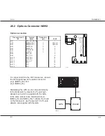
Страница 13: ... 12VDC FAN_ON RX_1_SQ CH_AUX_1 CH_AUX_2 RX_1_AF NMEA_OUT NMEA_OUT DSC_ALARM_ON X1 14 15 13 12 11 10 X2 9 8 7 6 5 4 1 3 2 To connect a GPS to the VHF transceiver connect the GPS signal lines to the options connector pin_4 NMEA_IN and pin_5 NMEA_IN Alternatively the GPS can be connected directly to the transceiver by means of a 15 pole high density D sub which is supplied with the radio in the same ...

Страница 14: ... from battery to N420 depends on the wire thickness but the voltage at the cable end at N420 should not be less than 18 volt 35355A 10 3 2 1 Spare 10A fuse Pin no Name Colour Pin 1 SUPPLY_ON Blue Pin 2 BAT Red Pin 3 BAT Black 2 8 Electrical Connections 2 8 1 Power Connectors Power Connectors Transceiver unit Name Battery N420 pin 1 SUPPLY_ON NC SUPPLY_ON pin 2 Battery 12VDC 12V pin 3 Battery 0VDC ...

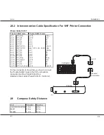
Страница 15: ...in 14 Slct in pin 6 BAT_0VDC pins 18 19 to 24 25 Gnd pin 7 LPT_Str pin 1 Strobe pin 8 LPT_D0 pin 2 D0 pin 9 LPT_D3 pin 5 D3 pin 10 LPT_D6 pin 8 D6 pin 11 LPT_Busy pin 11 Busy pin 12 LPT_Select pin 13 Slct pin 13 LPT_D2 pin 4 D2 pin 14 LPT_D5 pin 7 D5 pin 15 LPT_Auto_Feed pin 14 Auto fd For the connection to the printer you have to connect the 15 pole SUB D male to the VHF units printer connection ...

Страница 16: ...int path Select call by arrow right key 3 Transmit the call by keying Send call 4 The display will show in sequence TX CALL TX OK 5 The call is announced by the DSC modem Read the call info in RX LOG External test call The call is transmitted and received using the aerials This test also controls the hardware of transmitter and receiver boards 1 Hook off handset 2 Enter function menu Func dsc test...

Страница 17: ......

Страница 18: ......

Отзывы: