5 CIRCUIT DESCRIPTION AND SCHEMATIC DIAGRAMS
RT2048
5.2.
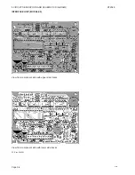
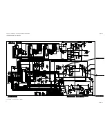
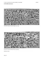
INTERFACE UNIT (MODULE 2)
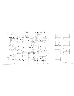
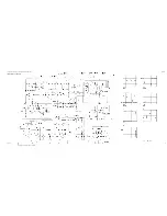
5.2.1. +5V POWER SUPPLY
The internal power supply for the logic circuitries is generated from the in8V power supply, by means of the
integrated voltage regulator U09. The input voltage for U09 is fed to pin 3 via D01, which secures an appropriate
voltage decay on C12 when the set is switched off.
5.2.2. BATTERY SENSE/RESET CIRCUIT
When the set is switched on, U07/1 which is coupled as a comparator will generate an appropriate reset signal for
the microcomputer U03.
U07/2 is configured as a comparator circuit sensing the level of the in13V supply voltage. When this voltage
drops below a certain level determined by R27, R20, R54, and D11 a „voltage low“ signal is generated on pin 1.
This action is detected by the microcomputer U3 which in turn will block the key function.
5.2.3. INDICATOR SUPPLY
The LED read-out intensity is controlled by means of a four-step voltage supply. Transistor Q02 acts as the emitter
follower buffer transistor. The base voltage level of this transistor, and so the output voltage, is controlled by means
of U08/4 and the programming resistors R07, R49, R47, and R55.
5.2.4. DISPLAY LATCHES
The display segments and the display power supply control inputs are buffered by means of three serial to parallel
registers included in the integrated circuits U04, U05 and U06. The information is latched-in by means of the internal
serial data bus controlled by the microcomputer.
5.2.5. READ-OUT
The information read-out is made by means of two seven-segment LED-displays D06, D07 and three individual
diodes for 1W, TX and US-mode 003, DID, and D12.
5.2.6. EEPROM-MEMORIES
The two IC’s U01 and U02 constitute the internal programmable memory. These circuits are controlled by the
microcomputer via the internal serial bus. The memories are used for set identification codes, private channel
programming etc.
5.2.7. MICROCOMPUTER
All the internal control signals are supplied by the microcomputer U03, either by means of the internal serial bus
or by individual control signals like the key function, power level etc. Besides the microcomputer reads the keyboard
information via the connector J01.
When a selcall unit is installed via J02, the control functions for this module and the alarm generation are created
by the microcomputer. The audible alarm is coupled to the loudspeaker by means of resistors R26, R40, and R46.
5.2.8. SERIAL INTERFACE
For use in the factory production, a serial interface to the microcomputer is implemented by means of U07/4 and
transistor Q01.
5.2.9. SQUELCH
The AF signal from the discriminator amplifier on RX/TX board is fed to the active squelch filter around U05/2, which
is a highpass filter with a roll- off frequency of 45 kHz. The signal is amplified about 6-8 dB.
The amplitude of the noise signal is adjustable from the front panel by means of the squelch potentiometer R10.
Q05 amplifies the signal to the squelch detector. If there is a noise signal (without carrier at the receiver), the
detector generates a DC voltage at pin 9 on U08/3. When this voltage increases to 0.6V, which is the same as the
voltage at pin 10 on U08/3, the comparator output goes low and the squelch mute message is generated via Q08.
The microcomputer U03 detects the message and generates the appropriate mute signals for the AF amplifiers.
5.2.10. AF FILTER/AMPLIFIER
The AF signal is led to the active filter around U08/1. The filter provides a frequency response of -6 dB/oct. in the
range of 0.3 to 3 kHz, and limits the signals outside this range.
Q04 is an emitter follower buffer amplifier, which supplies the earphone and the AF power amplifier. The uC controls
the mute function via Q06 and Q03. When Q06 is off the DC voltage at pin 3 and 1 is 8V and therefore Q04 is off.
The loudspeaker level is adjustable by means of the volume control R23.
Page 5-3
Содержание RT2048 VHF
Страница 1: ...INSTALLATION MANUAL SAILOR RT2048 VHF ...
Страница 4: ......
Страница 11: ...1 INTRODUCTION RT2048 Page 1 7 9403 BLOCK DIAGRAM ...
Страница 12: ......
Страница 22: ...2 INSTALLATION RT2048 Page 2 10 9346 626945 625473 ...
Страница 24: ...2 INSTALLATION RT2048 2 8 REAR VIEW OF VHF RT2048 25567 9350 Page 2 11 ...
Страница 26: ......
Страница 31: ...3 Service RT2048 3 10 PIN CONFIGURATIONS Page 3 5 ...
Страница 32: ...3 SERVICE RT2048 Page 3 6 ...
Страница 33: ...3 Service RT2048 Page 3 7 ...
Страница 34: ...3 SERVICE RT2048 Page 3 8 ...
Страница 38: ...5 CIRCUIT DESCRIPTION AND SCHEMATIC DIAGRAMS RT2048 Page 5 2 ...
Страница 89: ......
Страница 90: ...Thrane Thrane A S info thrane com www thrane com M2048GB Issue E 0820 ...

