


Chapter 3: Connecting power
40
Power cable selection
Calculating the maximum power cable extension
For 24 V DC operation
, the total impedance must be max. 500 m
Ω
, including
the ship’s source impedance.
For 12 V DC operation
, the total impedance must be max. 85 m
Ω
, including
the ship’s source impedance.
The total impedance is made up of the following:
•
the ship’s source impedance
•
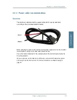
the cable impedance of the supplied power cable, including the
impedance in the joint of the two cables. In the following example, the
impedance of the cable and joint is set to 10 m
Ω
(1 m power cable). Note
that if the cable length or type is changed, the impedance will change
accordingly.
•
the extension cable impedance.
To calculate the maximum cable extension, do as follows:
1. First measure the ship’s source impedance as shown in Measuring the
ship source impedance on page 107.
2. Then find the resistance per meter for the cable type you are going to use.
For 4 mm
2
/AWG 11, the value is 4 m
Ω
/m at 20
°
C
For 1.5 mm
2
/AWG 15, the value is 10 m
Ω
/m at 20
°
C
For other cable types, refer to the data sheet for the cable.
3. Calculate the maximum allowed impedance in the extension cable as
follows:
Max. allowed impedance in extension cable = max. total impedance -
(measured source imp impedance of the supplied cable).
4. Then calculate the max. extension cable length as follows:
Max. impedance in extension cable (from step 3)
Max. length = 0.5 x impedance/meter (from step 2)
The length is multiplied by 0.5 above because there are two conductors in
the cable. If you need more length, you can double the maximum allowed
Содержание 500 FleetBroadband
Страница 1: ......
Страница 2: ...SAILOR 500 250 FleetBroadband INSTALLATION MANUAL ...
Страница 16: ...Table of contents xiv ...
Страница 22: ...Chapter 1 System units 6 IP handset and cradle ...
Страница 60: ...Chapter 3 Connecting power 44 Remote on off ...
Страница 100: ...Chapter 7 Troubleshooting 84 Logging of events ...
Страница 124: ...Appendix B Technical specifications 108 SAILOR FleetBroadband terminal ...
Страница 146: ...Appendix C Grounding and RF protection 130 Electrostatic Discharge ...
Страница 154: ...Index 138 ...