18
XL-MS196 Rev E · 2019-04-30 · Amendments and Errors Reserved · © SAF-HOLLAND, Inc., SAF-HOLLAND, HOLLAND, SAF,
and logos are trademarks of SAF-HOLLAND S.A., SAF-HOLLAND GmbH, and SAF-HOLLAND, Inc.
Component Replacement Instructions
9. Axle Alignment Procedures
1. When aligning axles, the suspension should be in a
natural, relaxed state, free of any binds. Before taking
measurements, and to achieve this relaxed condition,
ensure that the vehicle is unloaded. Then roll it back
and forth on a level floor. Avoid brake application.
The vehicle MUST be level from side to side as well as
from front to rear. Measurements should be taken from
the kingpin to the axle ends.
1. To properly align the suspension attached to the trailer,
ensure that there are no binds in the suspension.
2. Alignment can be achieved with an optical device
designed especially for this purpose or manually by the
following manner: Measure the distance from the kingpin
to the center line of the spindles on the front axles. It
is recommended that the spindle extensions be utilized.
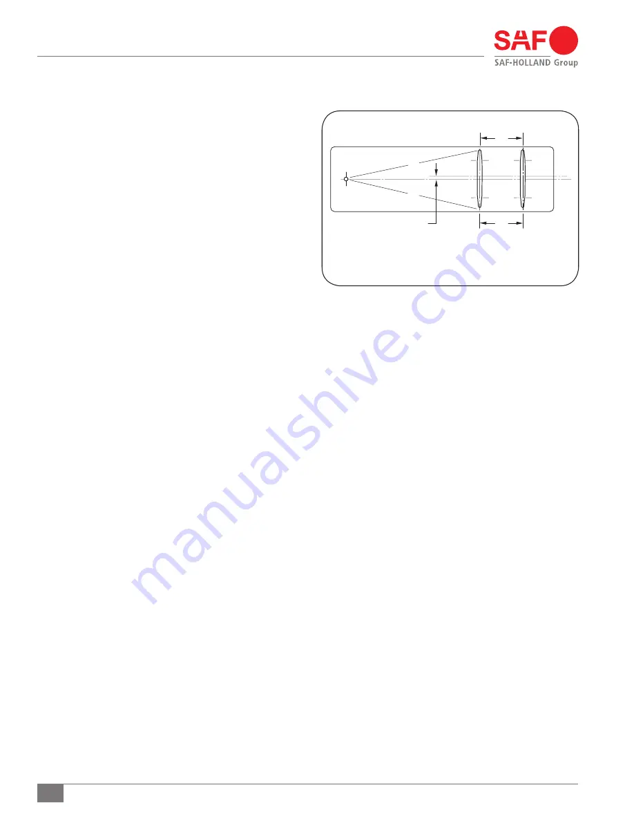
Dimensions A and B MUST be equal within 1/8"(3mm).
Dimension E is equal to the distance between the trailer
center line and the axle center line
(Figure 15)
.
3. Locate the rear axle to the forward axle and recheck the
king-pin alignment. Variance in “A” and “B” dimensions
would indicate axle alignment discrepancies.
4. Weld axles in accordance with NS-65-28 for TS Series and
NS-65-30 for the USR Series suspension.
10. Axle Alignment Tips
1. Always measure to the axle ends for accurate alignment.
2. Avoid measuring to the rims, suspension brackets,
brake drums and the like. This will only result in
improper alignment.
3. If difficulty is encountered in obtaining true alignment,
check and repair or replace worn or bent suspension parts.
Figure 15
A = B ± 1/8" (3 mm)
C = D ± 1/16" (1.6 mm)
E = 1/16" (1.6 mm)
A
C
B
D
E


