


176.12
.A03
7 - 8
ADJUSTMENTS
7
Revision 01 Date 14.11.2001
7.2.1
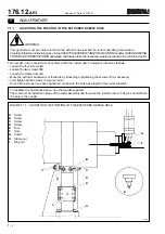
CUTTER HEIGHT ADJUSTMENT
- Position the three comparators (6) at 120
°
on the cam (1) as shown in the diagram (in zones 4).
- Set the comparators (6) to “zero”.
- Loosen the screws (2).
- Loosen or tighten the grub screws (3) to raise or lower the cam (1). Make sure the comparators give the same readings.
- Since the spindles (5) are attached to the cam (1), they are raised or lowered to the same degree as indicated by
the instrument.
To measure the correct distance between the cutter and the bottom of the cap, use the lower surface of the transfer
wheels as a reference. However they are 6 mm higher, as shown in figure 7.2.
FIGURE 7.2.1 - POSITION OF THE COMPARATORS
•
•
•
•
4
4
4
1
3
2
5
•
6
1
Cam
2
Screws
3
Grub screws
4
Position of the comparators
5
Spindles
6
Comparator
T0424
Содержание PMV 224
Страница 2: ...TABLE OF CONTENTS 176 12 A03 0 2 Revision 01 Date 14 11 2001 ...
Страница 4: ...TABLE OF CONTENTS 176 12 A03 0 4 Revision 01 Date 14 11 2001 ...
Страница 34: ...2 22 176 12 A03 Revision 01 Date 14 11 2001 2 MAIN FEATURES ...
Страница 42: ...3 8 176 12 A03 Revision 01 Date 14 11 2001 SAFETY EQUIPMENT AND PRECAUTIONS 3 ...
Страница 64: ...5 4 5 START UP 176 12 A03 Revision 01 Date 14 11 2001 ...
Страница 70: ...6 6 176 12 A03 Revision 01 Date 14 11 2001 6 OPERATING INSTRUCTIONS ...
Страница 126: ...8 30 176 12 A03 Revision 01 Date 14 11 2001 8 MAINTENANCE ...
Страница 128: ...9 2 176 12 A03 Revision 01 Date 14 11 2001 9 DECOMMISSIONING ...


