background image

Network Video Recorder Quick Start Guide 

27 


If the device is already activated, enter the user name and password in the login interface, 

and click the 

Login

 button. 


Figure 4-2


Login 


Step 3


Install the plug-in before viewing the live video and managing the camera. Please follow the 
installation prompts to install the plug-in. 


You may have to close the web browser to finish the installation of the plug-in. 

After login, you can perform the operation and configuration of the device, including the live view, 
playback, log search, configuration, etc.   


Содержание SABVISION NVR32

Страница 1: ...Network Video Recorder Quick Start Guide ...

Страница 2: ...Connections 14 2 3 1 Alarm Input Wiring 14 2 3 2 Alarm Output Wiring 14 2 3 3 Using Alarm Connectors 15 2 3 4 Controller Connection 15 2 4 HDD Storage Calculation Chart 16 Chapter 3 Menu Operation 17 3 1 Menu Structure 17 3 2 Startup and Shutdown 17 3 3 Activating Your Device 18 3 4 Using the Unlock Pattern for Login 19 3 5 Login and Logout 20 3 5 1 User Login 20 3 5 2 User Logout 21 3 6 Using the...

Страница 3: ...NO EVENT WILL OUR COMPANY ITS DIRECTORS OFFICERS EMPLOYEES OR AGENTS BE LIABLE TO YOU FOR ANY SPECIAL CONSEQUENTIAL INCIDENTAL OR INDIRECT DAMAGES INCLUDING AMONG OTHERS DAMAGES FOR LOSS OF BUSINESS PROFITS BUSINESS INTERRUPTION OR LOSS OF DATA OR DOCUMENTATION IN CONNECTION WITH THE USE OF THIS PRODUCT EVEN IF OUR COMPANY HAS BEEN ADVISED OF THE POSSIBILITY OF SUCH DAMAGES REGARDING TO THE PRODUC...

Страница 4: ...ference 2 This device must accept any interference received including interference that may cause undesired operation EU Conformity Statement This product and if applicable the supplied accessories too are marked with CE and comply therefore with the applicable harmonized European standards listed under the EMC Directive 2014 30 EU the LVD Directive 2014 35 EU the RoHS Directive 2011 65 EU 2012 19...

Страница 5: ...es Models SABVISION NVR SABVISION NVR16 SABVISION NVR32 Symbol Description Provides additional information to emphasize or supplement important points of the main text Indicates a potentially hazardous situation which if not avoided could result in equipment damage data loss performance degradation or unexpected results Indicates a hazard with a high level of risk which if not avoided will result ...

Страница 6: ...m the device turn off the power at once and unplug the power cable and then please contact the service center Preventive and Cautionary Tips Before connecting and operating your device please be advised of the following tips Ensure unit is installed in a well ventilated dust free environment Unit is designed for indoor use only Keep all liquids away from the device Ensure environmental conditions ...

Страница 7: ...Network Video Recorder Quick Start Guide 6 Chapter1 Panels Description 1 1 Front Panel 1 1 1 SABVISION NVR32 Figure 1 1 SABVISION NVR32 ...

Страница 8: ...quence The Enter button is used to confirm selection in menu mode or used to check checkbox fields and ON OFF switch 3 DIRECTION In menu mode the direction buttons are used to navigate between different fields and items and select setting parameters In playback mode the Up and Down buttons are used to speed up and slow down record playing and the Left and Right buttons are used to move the recordi...

Страница 9: ...ame Connections 1 POWER Turns green when NVR is powered up 2 HDD Flickers red when data is being read from or written to HDD 3 Tx Rx Flickers blue when network connection is functioning properly 4 USB Interface Universal Serial Bus USB port for additional devices such as USB mouse and USB Hard Disk Drive HDD No Name Description 1 LAN Interface 1 network interface provided 2 AUDIO OUT RCA connector...

Страница 10: ...put and menu 8 RS 485 Interface Half duplex connector for RS 485 devices 9 ALARM IN Connector for alarm input ALARM OUT Connector for alarm output 10 GROUND Ground needs to be connected when NVR starts up 11 AC 100V 240V 100V to 240VAC power supply 12 Power Switch Switch for turning on off the device 13 Network Interfaces with PoE function Network interfaces for the cameras and to provide power ov...

Страница 11: ...rnet interface 7 USB Interface Universal Serial Bus USB 3 0 ports for additional devices such as USB mouse and USB Hard Disk Drive HDD 8 Ground Ground needs to be connected when NVR starts up 9 Power Supply 12 VDC power supply for DS 7600NI I4 and DS 7600NI K4 and 100 to 240 VAC for DS 7600NI I4 P and DS 7600NI K4 P 10 Power Switch Switch for turning on off the device 11 Network Interfaces with Po...

Страница 12: ... Ensure the NVR is grounded Environmental temperature should be within the range of 10 to 55ºC 14 to 131ºF Environmental humidity should be within the range of 10 to 90 2 2 Hard Disk Installation Before you start Disconnect the power from the NVR before installing a hard disk drive HDD A factory recommended HDD should be used for this installation Tools Required Screwdriver 2 2 1 SABVISION NVR16 N...

Страница 13: ...e end of the data cable to the motherboard of NVR and the other end to the HDD Figure 2 2 Connect Data Cable Step 3 Connect the power cable to the HDD Figure 2 3 Connect Power Cable Step 4 Place the HDD on the bottom of the device and then fasten the screws on the bottom to fix the HDD ...

Страница 14: ...Network Video Recorder Quick Start Guide 13 Figure 2 4 Fix Hard Disk ...

Страница 15: ...larm Output Wiring To connect to an alarm output AC or DC load use the following diagram Figure 2 6 Alarm Output Wiring For DC load the jumpers can be used within the limit of 12V 1A safely To connect an AC load jumpers should be left open you must remove the jumper on the motherboard in the NVR Use an external relay for safety as shown in the figure above There are 4 jumpers JP6 JP9 JP10 and JP11...

Страница 16: ... cables are tight Step 3 Connect pluggable block back into terminal block 2 3 4 Controller Connection Figure 2 7 Controller Connection To connect a controller to the NVR Step 1 Disconnect pluggable block from the KB terminal block Step 2 Unfasten stop screws from the KB D D pluggable block insert signal cables into slots and fasten stop screws Ensure signal cables are in tight Step 3 Connect Ta on...

Страница 17: ...Rate Storage Used 96K 42M 128K 56M 160K 70M 192K 84M 224K 98M 256K 112M 320K 140M 384K 168M 448K 196M 512K 225M 640K 281M 768K 337M 896K 393M 1024K 450M 1280K 562M 1536K 675M 1792K 787M 2048K 900M 4096K 1 8G 8192K 3 6G 16384K 7 2G Please note that supplied values for storage space used is just for reference The storage values in the chart are estimated by formulas and may have some deviation from ...

Страница 18: ...o Loss HDD Detect Alarm Continuous Capture RS 232 VCA Normal Event Tag Sub periods External File Picture Picture VCA Search Behavior Search Face Search Counting Heat Map Alarm Hot Spare Advanced Search Plate Search Figure 3 1 Menu Structure The menu structure may vary according to different models 3 2 Startup and Shutdown Proper startup and shutdown procedures are crucial to expanding the life of ...

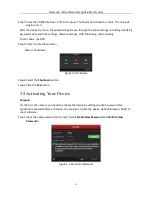
Страница 19: ...nd recording To shut down the NVR Step 3 Enter the Shutdown menu Menu Shutdown Figure 3 2 Shutdown Step 4 Select the Shutdown button Step 5 Click the Yes button 3 3 Activating Your Device Purpose For the first time access you need to activate the device by setting an admin password No operation is allowed before activation You can also activate the device via Web Browser SADP or client software St...

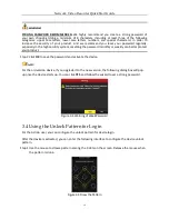
Страница 20: ...an better protect your product Step 2 Click OK to save the password and activate the device For the old version device if you upgrade it to the new version the following dialog box will pop up once the device starts up You can click YES and follow the wizard to set a strong password Figure 3 4 Warning of Weak Password 3 4 Using the Unlock Pattern for Login For the Admin user you can configure the ...

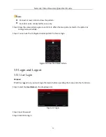
Страница 21: ... match the pattern is configured successfully Step 3 You can use the configured unlock pattern for future login Figure 3 6 Draw the Unlock Pattern 3 5 Login and Logout 3 5 1 User Login Purpose If NVR has logged out you must login the device before operating the menu and other functions Step 1 Select the User Name in the dropdown list Figure 3 7 Login Step 2 Input Password Step 3 Click OK to log in...

Страница 22: ...igure 3 8 Logout Step 2 Click Logout After you have logged out the system menu operation on the screen is invalid It is required to input a user name and password to unlock the system 3 6 Using the Setup Wizard The Setup Wizard can walk you through some important settings of the device By default the Setup Wizard starts once the device has loaded Check the checkbox to enable Setup Wizard when devi...

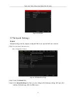
Страница 23: ...operly configured before you operate NVR over network Step 1 Enter the Network Settings interface Menu Configuration Network Figure 3 10 Network Settings Step 2 Select the General tab Step 3 In the General Settings interface you can configure the following settings NIC Type IPv4 Address IPv4 Gateway MTU and DNS Server ...

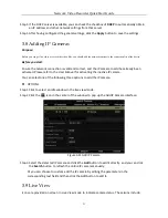
Страница 24: ...lready been activated Please refer to the User Manual for activating the inactive IP camera You can select one of the following three options to add the IP camera OPTION 1 Step 1 Click to select an idle window in the live view mode Step 2 Click the icon in the center of the window to pop up the Add IP Camera interface Figure 3 11 Add IP Camera Step 3 Select the detected IP camera and click the Add...

Страница 25: ...s already been installed If not please install a disk and initialize it You may refer to the user manual for detailed information Purpose Two kinds of record types are introduced in the following section including Instant Record and All day Record And for other record types you may refer to the user manual for detailed information After rebooting all the manual records enabled are canceled Step 1 ...

Страница 26: ...sub periods external file search Step 1 Enter playback interface Click Menu Playback or from the right click menu Step 2 Check the checkbox of channel s in the channel list and then double click to select a date on the calendar Step 3 You can use the toolbar in the bottom part of Playback interface to control playing progress Figure 3 13 Playback Interface Step 4 Select the channel s to or execute...

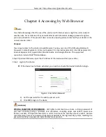
Страница 27: ...fari Mozilla Firefox and Google Chrome The supported resolutions include 1024 768 and above Step 1 Open web browser input the IP address of the device and then press Enter Step 2 Login to the device If the device has not been activated you need to activate the device first before login Figure 4 1 Set Admin Password 1 Set the password for the admin user account 2 Click OK to login to the device STR...

Страница 28: ... 4 2 Login Step 3 Install the plug in before viewing the live video and managing the camera Please follow the installation prompts to install the plug in You may have to close the web browser to finish the installation of the plug in After login you can perform the operation and configuration of the device including the live view playback log search configuration etc ...

Страница 29: ...Network Video Recorder Quick Start Guide 28 ...

Отзывы: