Saab TankRadar PRO Скачать руководство пользователя страница 24

Saab TankRadar

®


Pro

Mechanical Installation

2-11

Edition 2.

Ref. No: 306010E

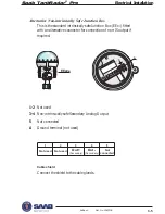
To mount the antenna do the following:

2.

Put the loose flange
on top of the antenna

3.

Tighten the flange to
the antenna by using
screws and nuts. Use
lubricating grease to
minimize friction
when the screws are
tightened.

Note!

Tighten the screws carefully to a torque
according to the recommended values in
table 1.
Tighten opposite screws in pair.

Note!

Use gaskets delivered by Saab. These gaskets are
optimized for use with microwave emitting equip-
ment. No other gaskets than Saab original may be
used for Process Seal antennas!

1.

Place a gasket on top of the socket and mount
the antenna.

Use one of the two gaskets delivered by Saab:

Teflon
or

Graphite for temperatures above 250 º C.

Содержание TankRadar PRO

Страница 1: ...User s Guide...

Страница 2: ...i Edition 2 Ref No 306010E Saab TankRadar Pro User s Guide Second edition Copyright September 1998 Saab Marine Electronics AB...

Страница 3: ...ed spare parts or any repair which is not made by Saab Tank Control Specific FCC Requirements USA only This device complies with part 15 of the FCC Rules Operation is subject to the following two cond...

Страница 4: ...diameter 50 mm 2 2 4 Tank flange diameter 65 mm 3 2 5 Mounting the Cone Antenna PTFE sealing 2 6 Mounting the Cone Antenna Quartz Sealing 2 8 Mounting the Cone Antenna Process Seal 2 10 Preparations 2...

Страница 5: ...Panel 3 9 Cables 3 10 Safety 3 10 Power Supply 3 10 Grounding 3 10 CENELEC 3 10 FM 3 10 System Overview 3 11 Display Panel 3 11 Analog Outputs 3 11 Digital Communication 3 11 Power Supply 3 11 Interna...

Страница 6: ...Pro Display Panel 5 1 Operation 5 1 Entering a Password 5 2 Adjusting the LCD contrast 5 2 Softkeys 5 3 Presentation of measured data 5 4 Selecting between different alternatives 5 5 Entering numerica...

Страница 7: ...Saab TankRadar Pro vi Edition 2 Ref No 306010E Display Panel 7 3 Analog Outputs 7 3 8 Troubleshooting 8 1 Display Panel Error Messages 8 2 User Input Errors 8 2 Internal Software Errors 8 2...

Страница 8: ...ging circuit boards or internal software Chapter 1 reviews some basic concepts of radar based level gaug ing Chapter 2 describes how to assemble a gauge and how to mount it on the tank Chapter 3 descr...

Страница 9: ...Saab TankRadar Pro viii Edition 2 Ref No 306010E...

Страница 10: ...s now and in the future The TankRadar Pro System The TankRadar Pro gauge offers a high degree of flexibility It can be used as a stand alone unit or it can be connected to various control systems You...

Страница 11: ...ne or two analog outputs depending on the particular hardware configuration As an option your TankRadar Pro gauge can be equipped with an easy to use display panel It offers basically the same functio...

Страница 12: ...is proportional to the distance to the liquid surface This signal can be measured very accurately allowing fast reliable and accurate level measure ments Saab TankRadar Pro uses an optimum microwave f...

Страница 13: ...by using information from previous measurements To further improve measurement accuracy Saab TankRadar Pro can utilize the benefits of Saab s Fast High Accuracy Signal Technique FHAST Multiple Echo T...

Страница 14: ...nna 100 4 Process Seal antenna 150 6 Process Seal antenna 2 Mechanical Installation For optimum measurement performance the TR Pro gauge should be mounted according to the socket requirements and the...

Страница 15: ...imum angle Cone antenna 1 Rod antenna 3 Process Seal antenna 3 Parabolic antenna 0 5 Minimum distance m Cone antenna 0 6 Rod antenna 0 3 Process Seal antenna 0 6 Parabolic antenna 0 6 Service space 55...

Страница 16: ...cone antenna 370 mm 8 cone antenna 395 mm 92 mm 4 cone antenna 140 mm 6 cone antenna 188 mm 8 cone antenna Dimensions Tools The following set of tools is needed for installation of a TankRadar Pro gau...

Страница 17: ...ke sure that all parts are clean and dry when mounted Tank flange diameter 50 mm 2 1 Put a gasket on the socket and insert the antenna 2 Mount the loose flange and tighten the screws 3 Insert the wave...

Страница 18: ...se gaskets under and above the flange adapter 2 Insert the antenna into the socket Mount the loose flange and tighten the screws 3 Insert the wave guide tube into the upper wave guide Make sure that a...

Страница 19: ...No gasket on top of this plate Mounting the Cone Antenna PTFE sealing 1 Mount the flange on top of the cone plate Make sure that the bottom side of the flange is flat and all parts are clean and dry...

Страница 20: ...cone antenna on the tank nozzle Tighten with screws and nuts 6 Insert the wave guide tube into the upper wave guide Make sure that the gasket at the lower end of the wave guide tube is in place 7 Pla...

Страница 21: ...s plate O ring Mounting the Cone Antenna Quartz Sealing 2 Secure the flange with the locking nut Make sure that the locking nut fits tightly to the flange 3 Mount the adapter on the sleeve 4 Secure th...

Страница 22: ...pins Adapter 5 Carefully fit the flange and the cone antenna on the tank flange Tighten with screws and nuts 6 Place the protection sleeve on the flange Mount the transmitter head Check that the guide...

Страница 23: ...ow d 0 5 mm Concave Ceramic window d 0 1 mm PTFE window d 0 5 mm Mounting the Cone Antenna Process Seal Preparations It is very important that the nozzle surface is flat The maximum deviation must be...

Страница 24: ...ws are tightened Note Tighten the screws carefully to a torque according to the recommended values in table 1 Tighten opposite screws in pair Note Use gaskets delivered by Saab These gaskets are optim...

Страница 25: ...12 Edition 2 Ref No 306010E Nut Wave guide tube Wave guide 4 Insert the wave guide tube into the upper wave guide 5 Mount the transmitter head onto the adapter 6 Tighten the nut and make sure that the...

Страница 26: ...P 5 2 N P 0 4 N P 0 0 1 N D 3 2 1 1 1 1 5 1 5 1 0 5 1 N D 2 1 5 1 5 1 I S N A e g n a l F i s P 0 5 1 i s P 0 0 3 4 1 1 5 1 6 5 1 0 1 c i m a r e C N I D e g n a l F 6 N P 0 1 N P 6 1 N P 5 2 N P 0 4...

Страница 27: ...ith the unit Make sure that the guide pin at the bottom side of the flange fits into the corresponding hole on the feeder See illustration 2 Mount the TRL2 adapter on top of the flange and tighten the...

Страница 28: ...lar rings Nozzle Lower flange Parabola 3 Mount the antenna feeder to the tank nozzle If necessary use angular rings inclination device to align the antenna within 0 5 o The rings can be used if the ta...

Страница 29: ...Mount the TCP tube into the TRL2 adapter 6 Mount the transmitter head Rotate the head and the TRL2 adapter to align the cover locking at the back of the transmitter head with the guide pins Note It i...

Страница 30: ...ical Installation Identication of Installed Options I Approval C Cenelec F FM P PTB X Other certificates II Power Supply A 100 240 VAC nominal power D 24 48 VDC nominal power III Primary Output 1A Non...

Страница 31: ...s Connection for Display Panel CENELEC EExi Optional EExe FM Intrinsically safe Explosion proof CENELEC EExe FM Explosion proof Power supply FM conduit fitting Flameproof enclosure Junction Box The st...

Страница 32: ...al Connections Non Intrinsically SafeJunction Box EEx e This Junction Box is for non intrinsically safe connections and power supply 1 2 Non intrinsically safe HART 4 20 mA primary analog output or TR...

Страница 33: ...e S t u O y r a d n o c e S P D S P D Intrinsically Safe Junction Box EEx i This Junction Box is for intrinsically safe connections and for connection of the Display Panel 1 2 Intrinsically safe HART...

Страница 34: ...e S t o N d e t c e n n o c Alternative Non intrinsically Safe Junction Box This is the standard intrinsically safe Junction Box EExi fitted with an alternative connector for connection of non IS out...

Страница 35: ...l Installation Field Bus Modem X1 1 2 3 4 5 Junction Box EEx e 100 240 VAC or 24 48 DC Connecting to a TRL2 Bus Interface Use a Field Bus Modem FBM for a Pro transmitter equipped with a TRL2 interface...

Страница 36: ...7 8 9 Voltage compli ance 7 30 V Input impedance 300 Ohm Connecting HART devices Active output internal loop supply Passive output external loop supply A hand held terminal or a HART modem should not...

Страница 37: ...r RTG 40 1 2 3 4 5 6 7 8 9 Hazardous Area Non Hazardous Area RTG 40 Zener barrier Analog instrument and or DCS system Hand held HART communicator HART interface Intrinsically safe conditions A hand he...

Страница 38: ...ound DPS DP Gnd Signal Connecting the Display Panel The Display Panel is intrinsically safe and may only be used when permanently mounted directly on the enclosure with two separate grounding wires Th...

Страница 39: ...allowed to be opened when energized Note Make sure that you do not mix up intrinsically safe and non intrincisally safe wires Power Supply You can use either DC or AC depend ing on what type power su...

Страница 40: ...nterface or Saab TRL 2 Bus interface The Saab TRL 2 Bus may only be connected to the non intrinsically safe EExe junction box Connect the serial data transmission cables to terminals 1 and 2 Power Sup...

Страница 41: ...X7 P 5 4 3 1 2 X1 L L PO PO X3 X4 X4 D DC40 X4 A AC40 X2 6 5 4 3 2 1 X5 X6 X7 X1 1 2 3 4 5 X3 X4 Non Intrinsically Safe EEx e Intrinsically Safe EEx i Internal Connections Option Description Board 0 N...

Страница 42: ...1 2 X1 L L PO PO X3 X4 IS40 X3 1A HM40 Primary Output Non Intrinsic Safety EEx e Intrinsic Safety EEx i Option Description Board 1A Non intrinsically safe HM40 IS40 HART 4 20 mA active 1C Non intrinsi...

Страница 43: ...on Description Board A Non intrinsically safe XA40 IS40 4 20mA active C Non intrinsically safe XA40 4 20mA passive Note This junction box is normally used for intrinsically safe connections This versi...

Страница 44: ...e task to start and configure the TankRadar Pro trans mitter When the gauge is mounted on the tank flange and the cables are properly connected you only need to run through a straightforward configura...

Страница 45: ...o install TankRadar Pro configuration software on your compu ter do the following 1 Start Windows and make sure that no applications are running If you run Pro Setup under Windows 95 upgrade Windows 9...

Страница 46: ...10E 4 Choose installation directory Program Files Saab is the default directory Click the Browse button if you want to specify another installation directory Click the Next button 5 Follow the instruc...

Страница 47: ...TankRadar Pro Pro Setup 4 4 Edition 2 Ref No 306010E 6 Specify the Com port and communication protocol you will use to connect the gauge Com port and protocol can be changed later 7 Finish the install...

Страница 48: ...Bar contains two buttons named Pro Setup and Saab TankRadar IO Master Server The last button refers to a communication program support ing Pro Setup Normally you do not need to open this window unless...

Страница 49: ...and service op tions You do not need to enter a password for viewing tank data To set a password do the following 1 Select Password from the Setup menu 2 Leave the Password input field blank if no pa...

Страница 50: ...on Logging on to a password protected system To log on to a password protected system do the following 1 Select Password from the Setup menu 2 Enter your password in the Password input field 3 Click t...

Страница 51: ...lowing to install and configure a Pro transmitter 1 Connect to a TankRadar PRO transmitter 1 Select New Tank from the File menu in the Main window 2 Enter a tank name to associate with the tank and cl...

Страница 52: ...ts see Electrical Installation or Choose Saab Modbus if your gauge is equipped with a TRL 2 Bus interface Make sure that you select the same protocol that was specified during the Pro Setup installati...

Страница 53: ...the transmitter did not respond to the old address and you can not find the Unit ID for example if the transmitter is lo cated far from the configuration PC do the following 1 Click the Scan Search bu...

Страница 54: ...ET FHAST filtering or strap table volume calculations 3 Mark the check boxes that corresponds to available software op tions that you want to enable Note The strapping table option can only be enabled...

Страница 55: ...o amplitudes Solid Products Setting this parameter optimizes the trans mitter for products which are not transpar ent for radar signals The effect will be more reliable handling of false echoes from b...

Страница 56: ...If this varaible is not set the trans mitter searches through the whole tank This parameter may typically be used for tanks with turbulent conditions 6 Click the Store button if no further settings a...

Страница 57: ...ription of the Tank Environment parameters in the Standard tab Note The Tank Environment parameter settings overrides some of the Holding register settings Tank Obstacles Tank Environment This option...

Страница 58: ...king of a moving surface Bottom echo always See description of the Standard tab visible if tank empty parameters Double bounce Some radar waves are reflected against possible the tank roof and back to...

Страница 59: ...e This function should only be used if DoubleSurface is set See description of Double surface If IgnoreTopSurface is set the lower surface will be presented as the product surface Show negative values...

Страница 60: ...ty or close to the bottom of the tank the level value full empty will normally be displayed as invalid Set this parameter to suppress the invalid display Note By setting this parameter the analog outp...

Страница 61: ...int G is defined as positive if you use an upper reference point above the TR Pro Reference Point For tanks with an ullage plug for hand dipping the Tank Ullage Refer ence Point dipping mark can be us...

Страница 62: ...e disturbing echoes in the upper part of the tank for example from the tank nozzle you can increase the Hold Off distance in order to avoid measurements in the region close to the antenna The Calibrat...

Страница 63: ...the analog out state on measurement error High the output current is set to 22 mA Low the output current is set to 3 8 mA Hold Last Value the output current is set to the present mea surement value a...

Страница 64: ...you want to check the calibration by measuring the output current do the following 1 Click the Calibrate DAC button 2 Read the instruction and the warning Note The analog output will be set to fixed...

Страница 65: ...Pro Pro Setup 4 22 Edition 2 Ref No 306010E 5 Click the Set to 20 mA button 6 Enter the measured output current and click the Store button 7 Click the Cancel button to close the window and finish the...

Страница 66: ...be used in cases where the tank shape deviates significantly from an ideal sphere or cylinder or when you require high accuracy Note The Strapping Table option can be used only if it is in the list o...

Страница 67: ...he tank manufacturer If the level volume table is based on a reference point that is different from your reference point you can adjust by adding corresponding offset values in the Adjusting Offsets f...

Страница 68: ...se echoes which are due to disturbing objects in the tank like beams agitators and heating coils The Spectra Threshold tab shows the amplitude of the meas ured signal along the tank This diagram is of...

Страница 69: ...o when foam is present or agitator is running Set amplitude threshold to approxi mately 30 of surface echo amplitude Note that these figures are approximate estimations Significant deviations from the...

Страница 70: ...f the currently selected point not the position of the added point To move points Select the point to be moved and drag to desired position or select the point and specify new position and amplitude i...

Страница 71: ...to filter out weak disturbances close to the tank bottom By using this technique the risk of locking to a disturbance echo close to the tank bottom is eliminated This technique is particularly useful...

Страница 72: ...measurement performance you may need to register interfering echoes as described below Note Registration of disturbing echoes requires that Saab s echofixer is enabled When should I register See the...

Страница 73: ...el as the disturbance In some cases weak disturb ing echoes can be filtered out by creating a noise threshold table see description of the Spectra Threshold window It may be necessary to register new...

Страница 74: ...hoes that you want to register as interfering echoes see recommendations on the previous page are added to the left hand table 4 When you have finished the registration of disturbing echoes click the...

Страница 75: ...y the gauge at the time of installation To manually add echoes do the following 1 Enter an ullage value in the Location field The entered value may deviate up to 100 mm from the actual position of the...

Страница 76: ...pen a tank file by choosing Open Tank from the File menu or by clicking the Open Tank button 3 Select the Tank Display option from the View menu or click the Display button in the PRO Setup Main windo...

Страница 77: ...olding Registers You can view the Input registers as well as the Holding registers by selecting the corresponding option from the Service menu The Holding registers can be edited Searching for the Pro...

Страница 78: ...thout pushing any button for 10 minutes the DP is automatically switched to View mode presenting the same measurement variable that was displayed last time View mode was open The Main menu contains th...

Страница 79: ...protected by a password The password is entered by pressing the three blank softkeys in a certain order maximum 12 charac ters Each figure refers to a particular softkey as illustrated below As defau...

Страница 80: ...down Submenus Softkeys Open the selected submenu Softkeys The softkeys have different meanings depending on which win dow that is open Use the arrow buttons to move the cursor up and down or sideways...

Страница 81: ...lue Back to View Menu Change Measurement Variable to be Displayed Change Display Mode Presentation of measured data When viewing measurement data you can use the softkeys to move between different vie...

Страница 82: ...cursor Move cursor down Save the current setting Selecting between different alternatives When you configure TankRadar Pro the softkeys will take on definitions which allow you to select specific item...

Страница 83: ...ick moves the cursor one step to the right Save the current setting Entering numerical values Use the button to enter the desired value Each click in creases the digit value one step from zero to nine...

Страница 84: ...y Standard Data NEXT BACK Viewing Level Data The View Menu The View Menu includes options for viewing tank and gauge related data Press the BACK button to return to the Main menu Use the or the button...

Страница 85: ...GRPH button allows you to switch between display modes Numerical measured data is presented as a value Bargraph the measured value is presented in a bar graph showing the current value Trend a set of...

Страница 86: ...opened when a transmitter is started for the first time You can always return to the Setup dialog if you want to change settings later on Display Panel This option allows you to set units for measure...

Страница 87: ...ton 3 To change your display panel password select the Password option and press the NEXT button This password must be entered in order to be able to change the transmitter configuration Follow the pr...

Страница 88: ...onfiguration windows The windows are automati cally opened in a predefined order To configure a new radar gauge using the Guided Setup option do the following 1 Choose Setup from the Main Menu Respons...

Страница 89: ...change the set of available options Saab s echofixer Mul tiple Echo Tracking MET Fast High Accuracy Signal Technique FHAST and strapping table volume calculation contact your local representative for...

Страница 90: ...r own reference point at the top of the tank Set G 0 if you want the flange as upper reference point G is defined as positive if you use an upper reference point above the TR Pro Reference Point For t...

Страница 91: ...Saab TankRadar Pro Pro Display Panel 5 14 Edition 2 Ref No 306010E Advanced Setup Use the Advanced Setup if you want to make a complete con figuration of the transmitter...

Страница 92: ...ded Advanced To configure a radar gauge using the Advanced Setup option 1 Choose Setup from the Main Menu Response a request for password is displayed 2 Enter your password and press the OK button 3 S...

Страница 93: ...ing MET Fast High Accuracy Signal Technique FHAST and strapping table volume calculation contact your local representative for a new start code 3 Check the list of enabled options Contact your local r...

Страница 94: ...ting Response the display returns to the Start Radar menu 6 Choose the Pipe Diameter option if you are using a Still Pipe antenna Enter the still pipe diameter by using the and buttons Note that the d...

Страница 95: ...lug for hand dipping the Tank Ullage Reference Point dipping mark can be used as upper reference point but you can use other reference points as well 2 The Tank Height R is defined as the distance bet...

Страница 96: ...The Hold Off distance defines how close to the RTG reference point a level value is accepted Normally the Hold Off distance does not need to be changed However if there are disturbing echoes in the up...

Страница 97: ...g output values that correspond to 4 mA and 20 mA respectively Select Alarm mode Select High if you want the analog output to lock on a value higher than 20 mA when an error is encountered Use Low if...

Страница 98: ...red value that corresponds to the 20 mA setting 6 Click the DONE button Now the D A calibration is finished and the analog output is no longer in fixed current mode 7 Select the Analog output2 option...

Страница 99: ...k the Add new false option if you want to manually add echoes This may be a useful option if for example there are known distur bances below the product surface which can not be detected by the gauge...

Страница 100: ...e list of registered disturbing echoes Mark the Clear list option if you want to remove the whole list of registered disturbing echoes This option may be useful if you want to create a completely new...

Страница 101: ...option allows you to setup the Pro transmitter for volume calculations You can choose between using either a predefined tank shape like a sphere or a horizontal or vertical cylinder or entering level...

Страница 102: ...pe software versions software and hardware configuration operation time error status and unit code Please provide this information if you contact Saab Tank Control for trouble shooting Echo Search Sta...

Страница 103: ...Saab TankRadar Pro Pro Display Panel 5 26 Edition 2 Ref No 306010E...

Страница 104: ...G to specify your own reference point at the top of the tank Set G 0 if you want the flange as upper reference point G is defined as positive if you use an upper reference point above the TR Pro Refer...

Страница 105: ...nd is defined as the distance between the zero level Tank Level Reference Point and the minimum accepted level Normally you set the C dis tance in order to extend the measurement below your zero refer...

Страница 106: ...nce point Lower reference point Examples The following examples illustrate how you can set the various tank distance parameters to suit your own preferred reference point settings Example 1 If you wan...

Страница 107: ...LID BACK U ullage L level G 0 R 10 5 m 0 U L 0 4 Height m 10 RTG reference point Upper reference point Lower reference point Example 2 If you want set Upper reference point equal to the G 0 TR Pro ref...

Страница 108: ...R 11 m 0 U L 0 4 Height m 10 RTG reference point Ullage reference point Upper reference point Lower reference point Example 3 If you want set Upper reference point at the G distance between ullage ul...

Страница 109: ...8 m 0 U L 0 2 m 0 4 Height m 10 RTG reference point Ullage reference point Datum plate Example 4 If you want set Upper reference point G distance between ullage at ullage reference point and RTG refe...

Страница 110: ...temperature 40 70 C 40 158 F Standard measuring range 0 50 m 0 165 ft Instrument accuracy 5 mm 0 2 Repeatability 1 mm 0 04 Processors Dual processor design 32 bit DSP 50 Mflops Signal processing FFT...

Страница 111: ...T4 FM Explosion proof IS Class I Div I 2 Groups A B C and D Pressure 1 to 20 Bar Vacuum to 300 Psi Antennas Rod Cone Process Seal and Parabola Antenna materials Teflon SS 316L HC4 Tantalum Viton Kalr...

Страница 112: ...ixels Four softkeys Text 7 lines with 16 characters Graphics up to 128 X 56 pixels Supports service functions Analog Outputs Type Galvanically isolated passive or active output external or internal lo...

Страница 113: ...Saab TankRadar Pro Technical Information 7 4 Edition 2 Ref No 306010E...

Страница 114: ...er has not locked on an interfering object Check that the mechanical installation is correct Serial communication failure Check the COM port setting in the Pro Setup program Check the serial communica...

Страница 115: ...to enter an unvalid value into a holding register Internal Software Errors This message indicates an error in the Display Panel software MAIN MENU View Service Setup ENT Internal Error Contact Servic...

Страница 116: ...resentative Second edition September 1998 Ref nr 306010 E Saab Tank Control Box 13045 S 402 51 G teborg SWEDEN Phone 46 31 337 00 00 Fax 46 31 25 30 22 e mail sales stc marine combitech se Internet ht...

Отзывы: