background image

2

TOOLS / TORQUE SPECS

WARNING! Correct tightening force on fasteners (nuts, bolts, 

screws) on your bicycle is important for your safety. If too 

little force is applied, the fastener may not hold securely. If 

too much force is applied, the fastener can strip threads, 

stretch, deform or break. Either way, incorrect tightening force 

can result in component failure, which can cause you to lose 

control and fall.
Where indicated, ensure that each bolt is torqued to 

specification. After your first ride, and consistently thereafter, 

recheck the tightness of each bolt to ensure secure attachment 

of the components. The following is a summary of torque 

specifications in this manual:
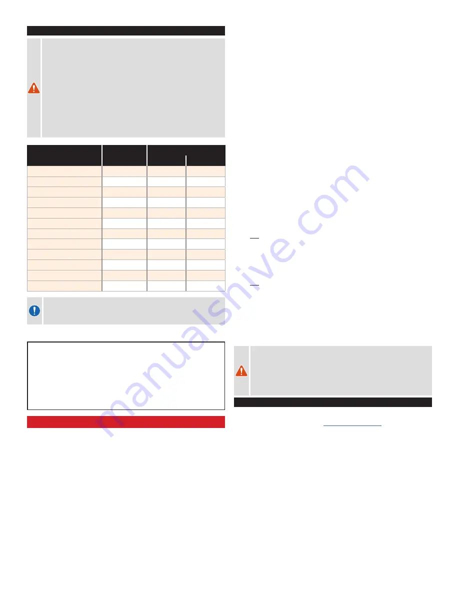
LOCATION

ALLEN KEY

TORQUE

in-lbf

Nm

SADDLE @ RAIL CLAMP

5

120

13.5

SEAT COLLAR

4

55

6.2

STEM

4

44

5.0

STEM COVER

2

1

0.12

DERAILLEUR HANGER

4

40

4.5

FRONT/REAR AXLE

6

133

15

SEATPOST Di2 COVER

2.5

7

0.8

WATER BOTTLE

3

25

2.8

STACK BOLTS

5

44

5.0

EXTENSION SOCKET

2.5

22

2.5

ARMREST CUPS

3

26.5

3.0

BLIP BOX

2.5

9

1.0

CAUTION: Ensure that all contact surfaces are clean and bolt 

threads are greased or have a threadlocking compound (refer 

to the instructions for each bolt) prior to installation.

The following tools are required for installation of this product:


„

2, 2.5, 3, 4, 5, 6mm socket-style Allen keys


„

Torque wrench


„

High-quality grease


„

Cable housing cutters


„

Carbon assembly compound (fiber paste)


„

Blue threadlocker

GENERAL NOTES ABOUT MAINTENANCE

The Shiv TT is a high performance bicycle. All regular maintenance, 
troubleshooting, repair and parts replacement must be performed by 
an Authorized Specialized Retailer. For general information regarding 
maintenance of your bicycle, please refer to the Owner’s Manual. In addition, 
routinely perform a mechanical safety check before each ride, as described in 
the Owner’s Manual.


„

Great care should be taken to not damage carbon fiber or composite 
material. Any damage may result in a loss of structural integrity, which 
may result in a catastrophic failure. This damage may or may not be 
visible in inspection. Before each ride, and after any crash, you should 
carefully inspect your bicycle for any fraying, gouging, scratches through 
the paint, chipping, bending, or any other signs of damage. Do not ride 
if your bicycle shows any of these signs. After any crash, and before you 
ride any further, take your bicycle to an Authorized Specialized Retailer 
for a complete inspection.


„

While riding, listen for any creaks, as a creak can be a sign of a problem 
with one or more components. Periodically examine all surfaces in bright 
sunlight to check for any small hairline cracks or fatigue at stress points, 
such as welds, seams, holes, and points of contact with other parts. If 
you hear any creaks, see signs of excessive wear, discover any cracks, 
no matter how small, or any damage to the bicycle, immediately stop 
riding the bicycle and have it inspected by your Authorized Specialized 
Retailer.


„

Lifespan and the type and frequency of maintenance depends on 
many factors, such as frequency and type of use, rider weight, riding 
conditions and/or impacts. Exposure to harsh elements, especially salty 
air (such as riding near the ocean or in the winter), can result in galvanic 
corrosion of components such as the crank spindle and bolts, which 
can accelerate wear and shorten the lifespan. Dirt can also accelerate 
wear of surfaces and bearings. The surfaces of the bicycle should 
be cleaned before each ride. The bicycle should also be maintained 
regularly by an Authorized Specialized Retailer, which means it should be 
cleaned, inspected for signs of corrosion and/or cracks and lubricated. 
If you notice any signs of corrosion or cracking on the frame or any 
component, the affected item must be replaced.


„

Regularly clean and lubricate the drivetrain according to the drivetrain 
manufacturer’s instructions.


„

Do 

not

 use a high pressure water spray directly on the bearings. Even 

water from a garden hose can penetrate bearing seals and crank 
interfaces, which can result in increased bearing and crank wear, which 
can affect the normal function of the bearings. Use a clean, damp cloth 
and bicycle cleaning agents for cleaning.


„

Do 

not

 expose the bicycle to prolonged direct sunlight or excessive heat, 

such as inside a car parked in the sun or near a heat source such as a 
radiator.


„

When placing the frame and/or bicycle in a repair stand, clamp the 
stand to the seatpost and not the frame. Clamping the frame can cause 
damage to the frame that may or may not be visible, which may impair 
the structural integrity of the frame.

WARNING! Failure to follow the instructions in this section may 

result in damage to the components on your bicycle and will 

void your warranty, but, most importantly, may result in serious 

personal injury or death. If your bicycle exhibits any signs of 

damage, do not use it and immediately bring it to your Authorized 

Specialized Retailer for inspection. 

WARRANTY

Warranty information is available from your Authorized Specialized Retailer. 
It is also available for download at 

www.specialized.com

.

Содержание TT 2020

Страница 1: ...USER MANUAL ENGLISH SHIV TT ...

Страница 2: ... accessories you are wearing exceeds this weight limit Failure to follow this warning may result in an accident which can cause serious injury or death GENERAL NOTES ABOUT ASSEMBLY This manual is not intended as a comprehensive assembly use service repair or maintenance guide Please see your Authorized Specialized Retailer for all service repairs or maintenance Your Authorized Specialized Retailer...

Страница 3: ...for any creaks as a creak can be a sign of a problem with one or more components Periodically examine all surfaces in bright sunlight to check for any small hairline cracks or fatigue at stress points such as welds seams holes and points of contact with other parts If you hear any creaks see signs of excessive wear discover any cracks no matter how small or any damage to the bicycle immediately st...

Страница 4: ... x 6 8 G UPPER HEADSET BEARING 38 x 27 2 x 6 3 H LOWER HEADSET BEARING 45 35 x 35 x 7 3 DESCRIPTION DIMENSIONS mm TOOL SIZE in lbf Nm I FRONT AXLE 6 133 15 J REAR AXLE 6 133 15 K FRONT DERAILEUR HANGER M4 x 12 2 5 18 2 0 L REAR DERAILLEUR HANGER M5 x 10 4 40 4 5 M JCT A BOX COVER M3 x 10 2 5 7 0 8 N JCT A PLUG FOR ETAP O Di2 BATTERY HOLDER P Di2 DROPOUT PLUG 1 A B C D E F G H I J K L P O N M ...

Страница 5: ... T NUT SLEEVE 11 x 5 1 x 10 Z T NUT THREADED M5 x 11 x 14 6 44 5 0 DESCRIPTION DIMENSIONS mm TOOL SIZE in lbf Nm AA STEM BOLTS M5 x 16 4 44 5 0 BB STEM NUTS M5 x 7 1 5 44 5 0 CC STEM COVER DD STEM COVER FRONT BOLTS M3 x 14 2 1 0 12 EE STEM COVER REAR BOLT M2 5 x 24 2 1 0 12 FF HEADSET TOP CAP BOLT M5 x 20 4 GG HEADSET TOP CAP HH ARM CUPS II ARM CUP BOLTS M5 x 8 3 26 5 3 0 JJ ARM CUP PADS 2 BB AA C...

Страница 6: ...p of the seat tube to the front side of the bottom bracket shell To remove the seatpost the EW RS910 must first be removed and the 1200mm wire unplugged TRAVEL OPTION If the seatpost will be removed repeatedly you can replace the 1200mm wire with a 700mm and a 500mm wire fig 3 A and an in line EW JC200 junction fig 3 B connecting the two wires ELECTRONIC SHIFT WIRING BASEBAR 4 1000mm EW JC130 SM J...

Страница 7: ... I Fig 7 Install the plug assembly upper G and lower H rubber plugs metal upper clip I plastic lower circlip J on the battery Insert the assembly into the seatpost with the battery plug facing down 8 EW RS910 500mm 1200mm FIG 8 Shimano Di2 Install the junction box in the seatpost Remove the cover from the back of the seatpost take the EW RS910 Junction A box and plug a 500mm wire into one of the t...

Страница 8: ...oo long we recommend using the 300mm seatpost WARNING For general instructions regarding the installation of the seatpost refer to the appropriate section in the Owner s Manual Riding with an improperly tightened seatpost can allow the saddle and seatpost to slide down which can damage the frame and cause you to lose control and fall WARNING Inspect the seatpost and seat tube to ensure that there ...

Страница 9: ...FIG 16 Install the fork Grease then install the lower headset bearing in the lower headset cup then run the fork into the head tube Grease then install the upper headset bearing down over the steerer tube and into the headset cup followed by the compression ring 17 HEADSET TOP CAP BASEBAR TOP CAP BOLT FIG 17 Install the basebar Install the basebar followed by the top cap and bolt The rear brake an...

Страница 10: ...of the top cap Ensure the brake line is properly positioned so there s no excess inside the frame and the handlebars will be able to rotate easily without tension from the rear brake housing 30 50mm 80mm 19 80mm HEAT SHRINK TUBING FRONT BRAKE HOUSING REAR BRAKE HOUSING 80mm NYLON TUBE FIG 19 Install heat shrink tubing and route brake housings To hold the nylon tube in position place an 80mm long s...

Страница 11: ...onical washer followed by the nut on the underside Repeat the steps for the 2nd stack 22 SLEEVE 6 OR 10 SHIM SHIMANO OR SRAM WIRE CONICAL WASHER SPACER STACK BRIDGE BOLT EXTENSION SOCKET 32mm BOLT Fig 22 40 145mm stack Install the 40 80 or 120mm spacer onto the basebar insert the sleeves under the basebar then thread two 32mm bolts into the spacer from below Place any additional spacers on top of ...

Страница 12: ...ter setup according to the brake manufacturer s instructions 26 EXTENSIONS MINIMUM INSERTION FIG 26 Install the extensions Insert the extension shifter wires in the extensions until they exit the ends of the extensions Route the extension shifter wires through the extensions loosening the stack bolts can help Depending on the shifters the wires will either have the exit the hole at the end of the ...

Страница 13: ...CER mm BRIDGE NO SHIM 6 SHIM 10 SHIM 5 10 20 40 80 120 10 0 22 27 27 32 NUT 5 27 32 32 37 NUT 10 32 37 37 42 NUT 15 37 42 42 47 NUT 20 42 47 47 52 NUT 25 47 52 52 57 NUT 30 52 57 57 62 NUT 35 57 62 62 67 NUT 40 27 32 32 37 SLEEVE 45 32 37 37 42 SLEEVE 50 37 42 42 47 SLEEVE 55 42 47 47 52 SLEEVE 60 47 52 52 57 SLEEVE 65 52 57 57 62 SLEEVE 70 57 62 62 67 SLEEVE STACK BOLT LENGTH mm INSERT SPACER mm ...

Отзывы: